 Tweet
Tweet
สรุปผมคงต้องทำเป็นปรีแหละ ผมฟังเพลงไม่เคยใช้ปรีเลย จาก DAC > Amp เลย EQ โปรแกรมอะไรก็ไม่ปรับ เสียงมาปล่อยอย่างงั้น
-
-
ทำแอมป์หูฟัง
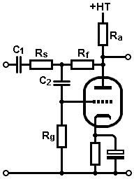
ดึง RF ไปหน้า บัฟเฟอร์เลยตครับ
ชุดoutput
C 15-20uf /R 470R (IMPEDANCE OUTPUT)
ตัดความถี่ประมาณ 16-22 HZ
-----
ส่วน R 1 K (current limiting resistor) ยังไม่เข้าใจว่ากำหนดยังไง
-----------------

When a headphone plug is inserted or removed from the jack, the possibility arises that the amplifier outputs will be shorted, if only briefly. Without current limiting, such a short could burn out opamps and/or output stage transistors. Rather than resort to complex current sensing schemes, figure 14 shows two common limiting mechanisms that protect against short-circuit damage: current limiting resistors and incandescent bulbs. Current limiting resistors set the minimum load that the amplifier can see ? typically 100 ohms, 1/2W. Output resistors will reduce the output power and increase the amplifier?s output resistance, but most headphones will be unaffected. Another option is to locate the current limiting resistors inside the feedback loop (figure 12) so that the effective output impedance of the amplifier is minimized from the feedback. See Headphone FAQs for more information about the impact of amplifier output impedance on headphone sound.
In place of a current limiting resistor, an incandescent lamp has the advantage of very low resistance when the filament is cold. Lamp filaments have a positive temperature coefficient. As increasing current heats the filament, the resistance also goes up, thereby reducing the output current. Choose lamps with voltage and current characteristics similar to that of the output stage. Incandescent lamps were once popularly deployed to protect loudspeakers from overdrive. The idea resurfaced as output limiting for headphone amplifiers in Ben Duncan?s PHONES-01 headphone amplifier project.
เครดิต
พวกแจ๊ค3.5 ตอนดึง-เสียบ จะมีช่วงช๊อตสัญญาณ-กราวน์ ลองนึกดูครับLast edited by tiger X-fi; 11 May 2014, 23:17:41.Comment
-
Rf10k/Ri 3.3KOriginally posted by carbon_za View Post
AV=1+10/3.3
AV=3.333
น่าเพื่ม Ci ลงกราวน์ (ตัดความถี่ต่ำออก)
1-10uf Frequency 48-4.8Hz (1 uf 48hz /10uf 4.8hz)
ครับLast edited by tiger X-fi; 12 May 2014, 10:36:11.Comment
-
Originally posted by ManiacMaew View Post เป็นรูปเป็ร่าง เริ่มร้องเพลงได้ละ
เป็นไงบ้างตอนนี้ เล่าต่อหน่อย
ให้ลองดูจุดต่างๆ ประมาณนี้
- ไฟจุดไส้หลอด ไม่รู้ว่าวงจรใช้แบบไหน ก็ลองวัด volt ก่อนและหลังเสียบหลอดดูว่าได้ค่าเท่าไหร่บ้าง
- ลองดูภาคบัฟเฟอร์ ให้ลองถอด C ที่ทำเป็น feedback ออก ไม่ต้องใส่
ปกติถ้าจะใช้ BUF634 จพใช้ร่วมกับ OPAMP เพื่อเพิ่มความสเถียร ลดความเพี้ยน
วาดวงจรแบบเร็วๆให้ดู ประมาณนี้

หรือ ลองไม่ต้องใช้ภาค buffer เลย แต่เพิ่มค่า C output อีกหน่อย เป็น 2.2uF-4.7uF
- วัดไฟที่ขา plate ของ triode แต่ละซีกดูว่าได้กี่ Volt (วัดเทียบ GND) เท่าๆกันไหมทั้ง 2 ซีกComment
-
กับหลอด
Negative feedback มันไปลงตรงจุดไหนครับ

---------
เจอแล้วครับ
------------
เข้าใจแล้ว Ck คิดอย่างไร
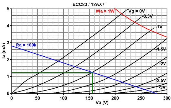
Rk ดูจากโหลดไลน์
Next choose a bias point in the usual way. In this case -1V looks good, for a quiescent anode current of 1.2mA. Use Ohm's law to find the value of bias resistor (Rk):
1 / 0.0012 = 833 ohms.
The nearest standard is 820R.
Ck
The capacitor needs to have a low reactance at all audio frequencies or phase shift and reduced open-loop gain could cause instability, oscillation or weird resonance effects. For a low roll-off of 10Hz:
C = 1 / (2 * pi * f * Rk)
C = 1 / (2 * pi * 10 * 820)
= 19uF
-----------
สตูรนี้ใช้ R-C Filter กดได้เลย...เหมือนเดิม
Last edited by tiger X-fi; 12 May 2014, 09:43:39.Comment
-
ขยันหาความรู้จริงๆ นับถือๆ
กำลังสงสัย RCอนุกรมกับขนาน มันใช้สูตรเดียวกัน?Last edited by keang; 12 May 2014, 11:41:35.Comment
-
หาทางไว้ดำน้ำครับพี่Originally posted by keang View Post
พวกแอมป์ IC พี่ก็เคยบอกไว้นี่Ri+Ci ดูแล้วเป็นเหมือนอะไหล่ตัวเดียวกัน
พอเป็นRk +Ck (ขนาน)นี่ชัดเลยว่าทำให้เป็นอะไหล่ตัวเดียวกัน
สงสัย...แบบนี้
Ri+Ci
C- R input
ก็น่าจะใช้แบบขนานได้เลย
หรือไม่ได้เพราะ Ri+Ci มี Rf /C- R input มี Rg มาเกี่ยวด้วยComment
-
- ใช้ACจุดไส้หลอด นอกจากลุ้นเรื่องhumแล้ว จะมีโอกาสเจอเอฟเฟคจากระบบไฟได้ง่ายขึ้น เพราะมันไม่มีตัวช่วยใดๆเลยOriginally posted by ManiacMaew
แต่ด้วยข้อดีบางอย่างของการจุดไส้หลอดด้วยAC ทำให้หลายๆคนพยายามหาวิธีลดnoiseให้ได้มากที่สุด
- หลอด6DJ8 จะมีข้อด้อย ตัวมันเองมีปัญหาเรื่องmicrophonic(อาจจะสะกดไม่ถูก) ส่วนใหญ่จะเลี่ยงไปใช้6922แทน
ถ้าเป็นเบอร์7308จะไม่มีปัญหานี้เลย+ได้ของแถมเรื่องเกนขยายของทั้ง2ข้างใกล้เคียงกันมากที่สุดด้วย แต่ก็แลกมาด้วยราคาที่สูงกว่าทั้ง2เบอร์นั้นด้วย
--------------------------------
> http://www.valvewizard.co.uk/OtherStuff.html
This graph shows how the frequency reponse of a typical ECC83 with 100k anode load and 1.5k cathode resistor, for different values of cathode bypass capcitor.
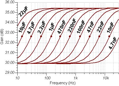
Music Reference RM-5 Mark1ถึง2 ใส่ Rk 1,000uF + 0.22uF (bi-cap) / Mark3ถึง5 ยังใช้1,000uFเหมือนเดิม แต่ไม่มี0.22uFแล้ว
ถ้าดูจากกราฟด้านบน 0.22uFนอกจากช่วยเรื่องเสริมประสิทธิภาพการทำงานให้Cอิเลคทรอไลติค1,000uFแล้ว ตัวมันเองยังชดเชยเกนขยายบางความถี่ไปพร้อมๆกันด้วย
--------------------------------
@ เสือ
> Triode Gain Stage
The Common-Cathode, Triode Gain Stage
The common cathode, triode amplifying stage is the fundamental building block of all amplifiers, and must be fully understood before we have any hope of designing a whole amplifier.
Because this particular topic is so essential to understanding guitar amplfiers, and because most people reading this will be newcomers, I have decided to explain the matter in full detail. This article is also the first chapter from my book Designing Valve Preamps for Guitar and Bass, Second Edition
Click here to view the chapter (1.5MB PDF)Last edited by keang; 12 May 2014, 15:13:55.Comment
-
กำลังดูอยู่เลยครับพี่
Ck = 1 / (2 * pi * f * Rk)

--------------
สงสัย Amplification Factor, ?


ใช่อย่างกรอบแดง หรือป่าวครับ
อ๋อ ต้องป็น เส้นเขียวที่จุด 0V
จุดตก 55v &155V
mu = VA/VG
=100/1
Amplification Factor =100
---------
เปลี่ยนเป็นเส้น 0.5
จุดตก 75V&125V
mu= 50/0.5
=100Last edited by tiger X-fi; 12 May 2014, 15:48:52.Comment
-
ลองดูหน้า6,7,8 ในรูปประกอบ มีจุดA,B / หน้า10-15
บทความเค้าละเอียดดีนะ มีบอกจุดที่ควรให้ความสำคัญควรคิดเผื่อไว้ด้วย
But there is something suspicious about this gain calculation. The grid curves are not
evenly spaced along the load line, so if we did our calculation near the top where the
curves are more stretched apart we would find a larger figure for gain than if we did
it near the bottom where they are more bunched up. So which bit of the load line do
we use? To answer this question we first need to understand how to bias the valve,
and from there discover how the choice of bias influences the distortion generated by
the circuit.
หน้า25
1.18: The Cathode Bypass Capacitor
Now that we have a better understanding of how a triode amplifier works
we can turn our attention back to the cathode bias circuit. We already know that
when the grid voltage is increased the anode current also attempts to increase, and
this in turn can be used to develop a much larger voltage signal at the anode. But the
anode current also flows in Rk, so when the anode current increases, the voltage
across Rk also increases, and likewise it must fall when the anode current falls. The
cathode voltage, therefore, attempts to follow the grid voltage, so the voltage
difference between grid and cathode will be less than the applied signal voltage. But
what the valve actually amplifies is the difference between grid and cathode, so by
adding Rk the valve now has a smaller signal to amplify and the gain of the circuit
will be less than the load line suggests. This effect is called cathode current
feedback or cathode degeneration, and as well as reducing the overall gain it also
reduces distortion and increases headroom.
Less distortion and more headroom may be just what we want in some circuits, but
not always. To eliminate the effect of cathode current feedback we need to stop the
cathode voltage from following the grid, but we don?t want to alter the DC bias
voltage. This is easily done by adding a cathode bypass capacitor, Ck, in parallel
with Rk, as shown in fig. 1.26. Any rapid rise in cathode current will now be
diverted into charging the capacitor, and if cathode current falls the capacitor will
supply the deficit from its own charge. Another way of looking at it is to say that the
capacitor decouples or bypasses to ground any AC signals on the cathode, so signal
current does not flow in the cathode resistor and the DC bias voltage remains
unchanged. With either explanation the result is the same; the cathode bypass
capacitor smoothes out changes in cathode voltage, helping to hold the cathode
voltage constant and thereby preventing cathode feedback.
Now, a capacitor will allow greater current flow at high frequencies than it will at
low frequencies. If we want the stage to have maximum gain at all audible
frequencies then the capacitor must be large enough to smooth out the lowest
frequencies of interest, and the stage is then described as fully bypassed. If the
capacitor is made relatively small then only high frequencies will be smoothed out
while lower frequencies will not. Therefore the stage will have maximum gain at
high frequencies and minimum gain at low frequencies, producing a treble boost,
and the stage would then be called partially bypassed. If the stage has no cathode
bypass capacitor then it is said to be unbypassed and will have minimum gain. This
ability to control the gain between lower and upper frequencies is an extremely
useful consequence of using cathode bias.
The exact relationship between the gain of the stage with frequency and the size of
the cathode bypass capacitor is not straightforward,3 but the shape of the frequency
response is; it forms a ?shelved? response like that shown in fig. 1.26. The frequency
at which the gain starts to rise from its lower level is given by:
Last edited by keang; 12 May 2014, 16:10:55.Comment
-
REPORT no.1 on ecc88/6dj8 pre-amplifier test

ไส้หลอดสว่างพอดีมั้ย อันนี้ปรับexposureกล้อง(มือถือ)เป็น0น่ะ ไม่งั้นแสงจากตรงอื่นกลบหมด

อันนี้ปรับexposureกล้องเป็น+1 มันมืดหง่ะ บอร์ดรอบๆจะเห็นไม่ชัดเอา (เอ๊ะ เห็นODGdacวางกองอยู่)
วางบนโต๊ะ สายไขว้กันรกหน่อย noiseอาจจะมาจากตรงนี้ก็ได้ ฮาๆ+ แต่ก็เตรียมไว้เปลี่ยนบอร์ดทดลอง
-ขา9 screen ปล่อยลอยไว้
-ผมใช้ic reg +-15voltน่ะ เพราะตอนเตรียมบอร์ดหลอดเตรียมค่าอะไหล่ไว้สำหรับไฟเลี้ยง+-15voltหมดเลย
-สายที่ใช้ในการทดลอง อย่างเทพ สายrca ฝั่ง output เส้นล่ะ30บาทจากเยอนารัล
สายฝั่งinputไปจิ๊กสายRGB ของเก่าของแม่มา
-อาการเรื่องoscillateตอนปรับโวลุ่มไม่สุดยังมีเหมือนเดิม volumeหน้าหลอดต้องปรับเกือบสุด volumeที่lm1875(หลังบัพเฟอร์หรือหลอด)
เปิดใหม่ปรับไป80+% เปิดนานๆ ลดเหลือประมาณ60%ได้
มีbackground noiseเบาๆ นั่งในระยะประมาณ1เมตรตอนกลางวัน พอได้ยิน ถือว่าไม่เงียบเท่าไร แต่ก็ไม่เยอะเกินจนรับไม่ได้
ุถ้าลดvolumeหน้าหลอดลงจะมีสัญญาณวิทยุแทรกแบบชัดเจน
-มีอาการเสียงแตกๆ เวลาสวิงมากๆ เช่นเสียงระเบิดในเกม หรือ กลอง-เบสในเพลงเวลามันขึ้นดังๆกระทันหัน เสียงเครื่องดนตรีบางชิ้นก็เป็น (ไม่แน่ใจว่าอะไรบ้าง)
อาการจะชัดเจน(คือแตกง่ายขึ้น) เมื่อไปลดvolumeที่ LM1875แล้วไปเพิ่มชดเชยในsoftware
-หลอดกับbuf634 อุ่นๆ จับได้ปรกติ
-เรื่องเสียงฟังคร่าวๆ ระหว่างเบิรน์ ไม่นับปัญหาด้านบน ก็ได้ imageเสียงที่ดีขึ้นจับตัวตนได้ง่าย(เทียบกับต่อตรง) หัวเสียงเน้นชัดขึ้น
เหมือนจะเน้นช่วงmid-bassถึงกลางล่างมากขึ้น
เรื่องรูปวง แปลกๆหง่ะ ไม่แน่ใจว่าจะเล่าไงดี มันเอามาเรียงใหม่หมดเลย เสียบซ้ายขวากลับกันมาตลอดเลยฮ่ะ เพิ่งรู้ตัว ต้องกลับไปลองใหม่
เรื่องหางเสียงจะว่ามันมีหางเสียงยาวขึ้นหรือหางเสียงมันลงแบบขั้นบันไดค่อยๆลงก็ไม่เชิงน่ะ ไม่รู้จะเรียกยังไง หางเสียงมันมีharmonicของมัน(ไม่รู้ใช้ศัพท์ถูกรึเปล่า)
ก็ฟังดูมีความเป็นดนตรี(?)มากขึ้น สนุกขึ้น ได้อารมณ์ขึ้นล่ะมั้ง
ถ้าเทียบsolidstateของLOD(ตัวที่เคยถ่ายรูปให้คุณmonolabดู) ตัวนั้นหางเสียงย้วยได้ใจกว่าปรีหลอดอีก
---------------
-ตอนนี้แก้ให้ใช้ไฟ dc จุดได้แล้วครับ ดันไปใช้ขด6Vacมาrectify ป้อนให้7906 ขาเข้า7906เลยสูงกว่า6voltนิดเดียวเปลี่ยนไปใช้ ขด9VacแทนOriginally posted by dracoV View Post
-วัดไฟจุดไส้หลอด ตอนใช้ไฟdcจุด ก่อนเสียบ 6.00Vdc หลังเสียบไปนานๆ5.99Vdc(เสียบใหม่ๆ6.00Vdcเท่าเดิม)
-ไฟจุดไส้หลอดAC 6.4Vac (ถึงจะเอาไฟมาจากขด6Vacก็เหอะ แต่ไฟบ้านมันแรงมันเลยแถมมาให้)
ไฟจุดไส้หลอดAC DCมีปัญหาเรื่องnoiseกับสัญญาณวิทยุแทรกเหมือนกัน แต่ไฟdc noiseจะเบากว่านิดหนึ่ง
ืตอนนี้ทดลอง2แบบ- ลองดูภาคบัฟเฟอร์ ให้ลองถอด C ที่ทำเป็น feedback ออก ไม่ต้องใส่
ปกติถ้าจะใช้ BUF634 จพใช้ร่วมกับ OPAMP เพื่อเพิ่มความสเถียร ลดความเพี้ยน
วาดวงจรแบบเร็วๆให้ดู ประมาณนี้
หรือ ลองไม่ต้องใช้ภาค buffer เลย แต่เพิ่มค่า C output อีกหน่อย เป็น 2.2uF-4.7uF
แบบ1

แบบ2

ทั้ง2แบบ มีปัญหาเรื่องnoise สัญญาณวิทยุรบกวน และเสียงแตก (แบบที่เล่าด้านบน)ทั้งคู่
background noiseและเสียงต่างกันนิดหน่อย
ไฟv+ ประมาณ 14.75 (เปิดไว้นานแหล่ะ เปิดใหม่ๆวัดได้14.8) ไฟที่ขาเพลท(ออกจากccs)ข้างหนึ่ง13.37 (ขา1)อีกข้าง13.67(ขา6)- วัดไฟที่ขา plate ของ triode แต่ละซีกดูว่าได้กี่ Volt (วัดเทียบ GND) เท่าๆกันไหมทั้ง 2 ซีก
----------------------------------------
-thxครับ เห็นราคาหลอดในอีเบย์แล้วช็อค ยังไม่ร่วมค่าส่งน่ะ แท้หรือre-labelเปล่าก็ดูไม่ออกOriginally posted by keang View Post
-คุณkeangคุณเสือ ไอ้โปรแกรม หรือเว็บที่ช่วยคำนวณเรื่องgainของหลอดมันอยู่ไหนเหรอ ผมค้นๆโพสต์เก่าแล้วหาไม่เจอ มึน
----------------
ขออภัย
ตอบช้าหน่อยน่ะครับ คืออยากจะเล่าตั้งแต่เมื่อวานแล้ว แต่หลายอย่างมันปนกันในหัว ต้องเรียบเรียง-แยกแยะแต่ละประเด็นออกจากกันก่อนLast edited by ManiacMaew; 12 May 2014, 16:17:17.Comment
-
- คุณเสือเค้ารวมไว้ให้ที่ หน้า1 ครับ
- ที่เล่ามา คือ ผ่าน2อย่าง หลอด+buf634 ?Comment
-
-ขอบคุณครับOriginally posted by keang View Post
-มีทั้ง2แบบ ตามรูปในโพสต์อ่ะครับ มีshortข้ามbuf634Comment
-
- ไส้หลอด สว่างมากน้อย ข้ามเรื่องนี้ไปก่อนครับ ให้มันทำงานได้ปกติก่อนค่อยกลับมาสนใจมันทีหลัง
- ผมว่า ลองทีละอย่างให้มันรู้เรื่องดีกว่ามั้ง จะได้ตัดปัญหาที่ไม่เกี่ยวข้องออกไปด้วย
- ตัว RM-5, ME-2 ผมเอา7DJ8ใส่ ไม่มีปัญหาเรื่องสัญญาณรบกวน ฮัมก็ไม่มี / แต่ของคุณแมวต่อบนบอร์ดทดลอง มันโดนกวนง่ายกว่าอยู่แล้วละ ไม่น่าแปลกใจ
ดูรูปแล้ว มีความรู้สึกว่า หลอดใส่ซ็อคเกท-ดันลงไปไม่สุดนะ ออกแรงดันหน่อยครับ เอาให้ลงไปให้สุดเลย-ให้ตูดหลอดแนบกับซ็อคเกท
ไม่แน่ ปัญหาบางอย่างอาจมาจากตรงนี้
Last edited by keang; 12 May 2014, 16:37:54.Comment
-
รูปวงจร DC Blocker ของเครื่องเสียงยี่ห้อ Crown และ Bryston ใช้

รูปวงจร DC Blocker แบบง่ายๆ แพร่หลายตามเวปDIY

-------------------------------------------
> Elliott Sound Products : Blocking Mains DC Offset
แนะนำให้เข้าตามลิ้งค์ เพื่ออ่านรายละเอียดของบทความทั้งหมด
Introduction
A varying DC offset on the AC mains is no longer uncommon. There are many ways that a DC offset can be created, with most being totally outside the control of those who have to try to eliminate it, or put up with the mechanical noise created in toroidal transformers.
There are a few older household appliances that can create a DC offset, although most are (probably) no longer permitted due to increasing problems caused by the DC component. This is more than compensated by various industrial processes, which for one reason or another manage to unbalance the mains supply sufficiently to cause problems.
Most of the time, the DC offset is transient - it appears for a short while, then goes away again. When it is there, toroidal transformers may complain loudly, by making growling or buzzing noises. It is important to understand just how this happens, and what can be done about it if it causes problems.
While the common solution found on the Net appears simple, there's a lot more to it than may seem to be the case. The operation is not intuitive, so while you may think that you know how it works, you could easily be mistaken.
It's also worth noting that DC is usually not a problem with toroidal transformers of 300VA or less. Their primary resistance is usually high enough that any DC will have little effect. With larger transformers (500VA and above), the DC resistance is usually so low that even a very small offset will cause mechanical noise due to saturation.
How DC Appears on the Mains
There are any number of different machines that can create a mains supply DC offset. Most will be totally outside your control, many DC "events" will be transient in nature, but one common theme applies - they will all load the mains supply asymmetrically for a period of time that ranges from a couple of cycles to minutes at a time. Figure 1 shows a typical (small) example that you may even have in your house - the transformer (shown within the dotted line) is your toroidal transformer. Many older hairdryers (and some heat guns as well) had a switch for "half power" that simply switched a diode in series with the mains. For a 240W element at 240V, that equates to a resistance of 240 Ohms (example only - actual power will vary widely).
If a diode is switched in series with the heating element, this reduces the voltage and hence the power (actual power will be almost exactly half). However, by half-wave rectifying the mains in this manner, there is an inevitable interaction with the mains impedance.
Figure 1 - Half-Wave Rectified Appliance, Transformer & Mains Wiring

The arrangement shown above assumes that the mains has zero impedance. Actual impedance is shown as R1, which varies from one house to the next. The value of 800 milliohms was chosen because this is what I measured at my workbench. Your mains may be better or worse than this.
After the asymmetrical load has done its job, a simulation shows the positive peaks of the 240V AC waveform reach 338.35V, but the (unloaded) negative peaks reach the proper value of 339.28V. This is a tiny bit less than the theoretical value of 339.41V because of the transformer load resistance and simulator resolution. The difference between the peak voltages is 0.93V, but the mean (average) DC voltage is -275mV. It is the mean value that appears as "DC" on the mains. It can also be measured, but to do so requires that one works on live components. This is not recommended as it is inherently dangerous. However, if you must (and PLEASE take extreme care), you need a 100k resistor and a 10uF non-polarised capacitor, wired in series. Connect this circuit across the mains (power off!), and connect a DC voltmeter across the capacitor. This attenuates the AC enough to prevent the front-end of the meter from being overloaded, and the DC voltage is easy to measure. Expect to see the DC vary around the zero voltage, with a normal variation of +/-25mV or so (typical - residential areas). The alternative method is to measure the DC across the diode/capacitor network in the circuit of Figure 3. Do not connect or disconnect the meter with the circuit live, and use alligator clip leads to make the connections.
With a half wave rectified load, the mean DC level is 275mV as described above - polarity is not important, because either polarity will be as bad as the other. If a transformer has a primary DC resistance of 2 ohms, there will be an effective DC current of 137.5mA in the primary. This is many times the current needed to cause the core to saturate during the negative half cycle of the AC waveform. Remember that with a toroidal core, saturation is a "hard limit". Because there is no air gap (intentional or otherwise), when the saturation limit is reached, inductance falls and current rises rapidly.
Tests were done using a 500VA toroidal transformer with very close to the example values given above. With 240V AC mains, 50Hz, 264mV DC offset created by DC injection (see Figure 6), and at no load, the current was seen to rise from 16mA to 218mA. The test was done at no load because this is the worst possible case. As load increases, the effective primary voltage falls - the voltage dropped across the winding's resistance is "lost" to the transformer. 264mV DC offset causes a current of 132mA DC in the transformer primary. This is probably the maximum offset that you will encounter in real life, although some areas may be worse. I have no data on this.
Use a Capacitor
Logically, using a series capacitor will block any DC. Capacitors cannot pass DC, so the waveform will re-centre itself to ensure that there is no offset. This happens regardless of how the DC offset was created, and is insensitive to waveform distortion. It's only when we do a few calculations that the real problem shows itself. Naturally, we want the lowest possible voltage to appear across the capacitor. We also want to ensure that a series resonant effect is not created where the capacitance and transformer primary inductance create a tuned circuit at (or near) the mains frequency. Such a circuit will appear as an extremely low impedance across the mains, and can generate voltages sufficient to destroy any capacitor (explosively!) and perhaps even the transformer winding insulation. Then the fuse or circuit breaker will blow, but the damage is done.
So, we need a capacitor (or a circuit) that will ...
- Handle the maximum current the transformer will draw (high ripple current)
- Drop the smallest possible voltage (large value of capacitance)
- Not cause series resonant effects
- Last for the expected life of the equipment
That's a tall order! Taking each point in turn, we can look at the likely requirements ...
Ripple Current - It may seem that we need to know the amplifier power rating, and also that of the transformer. We already know that the transformer will be subjected to considerable inrush current, both to set up the magnetising current and initially charge the filter caps. At this point, use of a soft start circuit (see Project 39) is highly recommended.
For the sake of the exercise, we'll use the 500VA transformer as shown in Table 1. Maximum long-term input current is ...
I = VA / V = 500 / 240 = 2.08A
From the DC perspective, the most critical region is at no-load. The saturation effects are greatly reduced when we are drawing significant current, so we will hopefully be able to simplify the circuit.
Voltage Drop - Now that we have the current, we can work out the required capacitance. Keeping the RMS voltage across the capacitor below 1V would seem like a reasonable figure, and I'd suggest that the maximum current of interest is around ? of the full load current - about 500mA. This means that capacitive reactance must be 2 Ohms or less. Remember that we can use Ohm's law to make these calculations - at least up to this point. Calculating the capacitance needed means that we use the capacitive reactance formula, suitably rearranged
C = 1 / ( 2 * pi * f * Xc ) where f is frequency and Xc is capacitive reactance
C = 1 / ( 2 * pi * 50 * 2 ) = 1,590uF
That's a fairly large capacitance, and can only be economically realised using an electrolytic capacitor. This raises a new quandary - electrolytic caps can operate for many years without a polarising voltage, but only at very low voltages. This means that the maximum voltage across the cap(s) must be limited, or they will fail. To be sensible, it will be necessary to use a pair of electrolytic capacitors, wired in "anti-parallel". A normal series connection with the two negative (or positive) terminals joined will also work, but reduces the available capacitance and maximises ripple current through both caps. Nonetheless, this may be preferable (see conclusion). The traditional way to limit the voltage is to use a number of high current diodes in parallel with the caps.
Series Resonance - The primary inductance can be calculated (close enough) by knowing the no-load current. All the primary current at no-load is the result of magnetising loss, and this is nothing more than that current which is drawn by an inductor when connected to the mains supply. The approximate effective inductance can be calculated, and it will generally be in the order of 40H or more. To save anyone the trouble, we have already determined that we need about 1,500uF, so series resonance can be discounted. The amount of capacitance is simply far too large to be able to resonate at 50Hz (or 60Hz) unless the transformer's inductance is impossibly small. However, it's still worth checking!
f = 1 / ( 2 * pi * ? L * C ) where f is frequency, L is inductance and C is capacitance
f = 1 / ( 2 * pi * ? 40 * 1,500u ) = 0.649 Hz
The resonant frequency of the network is well away from the mains frequency, so series resonance is not a problem.
Longevity - Inrush current can be very much higher than the nominal full power current, so the capacitor(s) require protection against over-current. The simplest has already been mentioned - the diodes that limit the maximum voltage across the caps will also limit the capacitor current. As current increases, so too does the voltage across the capacitors. The diodes will conduct if the voltage exceeds the forward voltage of either pair of the two series diodes. These diodes must be capable of withstanding the maximum peak current expected. This may exceed 50A for a brief period, and again, use a soft-start circuit!
Conclusion
Figure 8 shows the final (and recommended) design. While electrolytic caps can withstand a small reverse voltage (around 1V is typical), in the interests of longevity it is probably better to use the caps in series. Being in series, the capacitance of each must be doubled, and as shown the total effective capacitance is 2,350uF. Larger electrolytics can be used if desired, and a medium voltage rating will be required to ensure they can withstand the ripple current (this must be verified! ). Make sure the caps are well clear of anything that gets hot in operation.
Figure 8 - Recommended Design

While it is probable that using the caps in parallel as shown earlier will work reliably for many years, this is not something I can guarantee, because I've not performed any form of accelerated ageing process to the circuit. Not having used the circuit in any of my own equipment, I have no data either way.
The circuit and design processes described here will work for any size transformer. In most cases, the circuit shown in Figure 3 will be fine for any transformer from 500 to 750VA. DC stoppers are usually not needed in smaller toroidal trannies because their primary DC resistance is high enough to limit the (usually small) DC component so the DC has very little effect.
There is something to be said for the use of only two diodes in reverse-parallel, combined with larger capacitance (double the amount shown here). Voltages are lower, but the larger capacitors will be physically smaller because lower voltage parts can be used as ripple current is reduced. The critical component is the capacitor - that is the key to blocking DC.
It has been suggested elsewhere* that diodes have a forward voltage, and that is sufficient to block the DC component of the mains waveform. This is perfectly true for a low DC voltage by itself, but not with AC present at the same time. I tested the circuit using diodes alone and it does ... exactly nothing. The diodes are used to protect the capacitor bank, but it is the capacitor that blocks the DC - not the diodes. While the circuit may work with a small capacitance, it still has to be large enough to ensure that the normal idle current of the transformer cannot create a voltage drop such that the diodes conduct. The smallest capacitance that could be used with the circuit shown above is probably about 440uF (2 x 220uF caps), but this will be marginal. The caps may be unable to withstand the ripple current by the time the diodes conduct, and overall effectiveness is seriously diminished.
Additional tests I performed used only diodes (no effect whatsoever), and a 22uF and 1uF capacitor, and both of these were completely useless. Actually, they were worse than useless, by actually creating a DC offset! Without a very detailed examination, it appears that the small capacitance is only capable of averaging the slightly different forward voltages of the diodes, resulting in a few millivolts of offset. Because the cap is not big enough to maintain the AC component to a value well below diode conduction voltage, this small DC voltage then becomes an offset. With 1uF, transformer idle current rose to about 25mA without any external DC, and was 170mA when DC was added (same setup as used for all other tests). Idle current was a little less than this with the 22uF cap, but not by very much.
It's worth noting that the mains "DC" observed (measured across the diode/capacitor network) varied by about ?25mV worst case - at least while I was watching!. However, this was measured in a residential area, and there is no doubt that much higher voltages occur from time to time. I expect that a circuit that has been tested to work with over 250mV as shown here will be more than sufficient for most installations.
The circuit as shown will also work perfectly with 120V 60Hz, but it would be wise to increase the capacitance (double the value shown here). Although the caps will work better with the higher frequency, the transformer idle current will be almost double that of a 220-240V transformer.
Safety
Electrical safety is of utmost importance with a circuit such as that described here. Never rely on the electrolytic capacitor outer plastic sleeve for insulation. All parts must be meticulously mounted, with special consideration to personal protection from live components and separation of all low voltage conductors from anything at mains potential.
Ideally, the entire circuit will be afforded an earthed metal cover plate. This protects against accidental contact, and ensures that should a capacitor choose to explode, it's intestines will be confined to a small area, rather than scattered throughout the amplifier chassis.
Regardless of whether the circuit is installed in the active (live) or neutral conductor, the insulation requirements do not change. There is no guarantee that the neutral will always be at earth potential. A mis-wired mains lead, power board, extension lead or power outlet will all make the active become the neutral and vice versa. Because of this, you must allow for the worst case and insulate accordingly.
While testing your new DC Blocker, you must use insulated alligator clip leads for your multimeter. All connections must be made with power off. The clip leads allow you to make connections that don't rely on you holding probes in position. A slip can cause a lot of damage!.
If at all possible, use a Variac to power the circuit for the first time. This allows you to monitor everything and power can be removed before any damage is done if you made a mistake. If a Variac is not available, use a 100W lamp in series with the mains lead. Ideally, the secondary windings of the transformer should be disconnected while you are testing.
-------------------------------------------
ใครทำตัวนี้ไว้ใช้งาน อย่าลืม คำนวน ค่าทนกระแสของไอโอดและค่าC ให้เหมาะสมกับโหลดที่เอาไปต่อใช้งานด้วยOriginally posted by dracoV
-------------------------------------------
เวป-กระทู้ ที่มีคนทำ DC Blocker
> diyAudio - Glen B : DC blocker diode/cap orientation
> diyAudio - mhouston : DC blockers and mains filters
> OAMLabs F45mk2 Mains Filter and DC Blocker
> Mono and Stereo High-End Audio Magazine : AC/DC ... or a Highway to Hell
> Tweakers' Asylum : Naive questions re d-i-y
> XtremePlace - vertigo_ blues : Dc blocker
> The Art of Sound - HighFidelityGuy : DIY DC blocker?
> nuummie : DC Filter ที่ผมทำ
> nuummie : DIY DC Blocker สำหรับไฟ AC
> htg (too ninja) - Goda Takeshi : การใส่ capacitor ในปลั๊กกรองไฟ
> ocz - osxp : หน้า287 #5725
รวมรูป วิธีการทำDC Blocker จากgoogle
> google search : dc blockerLast edited by keang; 13 May 2014, 14:25:06.Comment


Comment