Announcement

Collapse
No announcement yet.

โมให้ดีกันเยอะแล้ว มาม๊ะ....มาโมให้"เจ๊ง"กันดีกว่า

Collapse
X
 
  • Filter
  • Time
  • Show
Clear All
new posts

  • ผมทำแอมที่สั่ง pcb มาจาก cmoybb.com ครับ


    แต่ปรากฏว่า เปิดแล้วไฟมันก็วูบครับ
    ต่อกับถ่าน 9V ตอนแรกวัดไฟได้ 8V กว่าๆ แต่พอเปิดปุ๊บ ไฟเหลือ 4V กว่าๆครับ
    ถามไปทางเว็บ เค้าตอบว่า มีจุดที่มันช๊อต แต่เค้าดูลายที่บักรีแล้วดูโอเคดี

    ผมจะสามารถนั่งไล่หาได้ยังไงครับ ว่าจุดไหนมันช๊อตอ่าครับ ?
    หรือพอจะมีใครรับซ่อมมั้ยครับ ?

    ขอบคุณครับ

    Comment


    • Originally posted by nattapong29
      ตอนนี้เสียงออกแล้วครับ เดี๋ยวยังไงวัดไฟตรงจุดต่างๆแล้วจะเอามาลงใว้ดูครับเป็นข้อมูล
      Originally posted by tiger X-fi
      ^
      เป็นที่ตรงไหน...แล้วแก้ยังไงครับ
      ขอบคุณครับ
      ยังงัยถ่ายรูปการ์ดสภาพปัจจุบันให้ดูด้วยน่ะครับ

      Originally posted by nattapong29
      REG 5V เอาพัดลมเล็กๆมาเป่าแล้วลองดูอาการไปก่อนครับ
      REG ตัวเล็กกับตัวใหญ่อันไหนดีกว่ากันครับตัวเล็กจะสูญเสียไฟน้อยกว่าหรือไม่ครับตัวเล็กๆ
      reg 5v ร้อนมากขนาดไหนครับ ?
      ตัวเล็กตัวใหญ่ ตัวมันดรอปไฟเท่ากัน แต่ต่างกันที่จ่ายกระแสเอ้าท์พุทได้ต่างกัน

      Originally posted by nattapong29
      เห็นมีแบบจ่ายได้1.5A ด้วย แบบจานบินขนาดย่อมๆที่ท่าน keang เคยเอารูปมาให้ดูพอจะหาซื้อได้ง่ายมั๊ยครับ
      1.5A คือ ตัวถังTO-220 ปรกติจ่ายได้1A แต่เมื่อติดฮีทซิ้งค์แล้วทำให้จ่ายแบบOverload Maximumได้1.5A
      แต่โดยปรกติถึงจะติดซิ้งค์ เค้าจะคิดกันแค่1Aตามสเปคที่ตัวมันจ่ายได้จริง

      ตัวจานบิน บ้านหม้อน่าจะมีขายครับ ลองไปดูสหพิพัฒน์กับนัฐพงษ์ก่อน ถ้าไม่มีค่อยไปดูที่บ้านหม้อพลาซ่า
      ตัวการ์ดจะมีที่ใส่ตัวจานบินเหรอครับ ?


      ------------------------------------------------------------


      - Alps RK097 Volume Control and On/Off Switch
      - Bass Boost Toggle Switch
      - DC Auxiliary Power Jack
      - Automatic On/Off (senses headphone cord)
      - Texas Instruments OPA2227 Opamp in Gold-Plated DIP Socket
      - Texas Instruments TLE2426 Precision Virtual Ground (2x optional)
      - Decoupling Capacitors on All IC Supply Pins
      - Custom 2-Layer PCB: Compact Layout with Ground Plane


      Originally posted by iPol2n
      แต่ปรากฏว่า เปิดแล้วไฟมันก็วูบครับ
      ต่อกับถ่าน 9V ตอนแรกวัดไฟได้ 8V กว่าๆ แต่พอเปิดปุ๊บ ไฟเหลือ 4V กว่าๆครับ
      ถามไปทางเว็บ เค้าตอบว่า มีจุดที่มันช๊อต แต่เค้าดูลายที่บักรีแล้วดูโอเคดี
      ดูจุดบัดกรีก็ไม่น่ามีไรช๊อทน่ะ
      ถ้าไม่ใช่เรื่องจุดบัดกรี+ใส่อะหลั่ยผิด ก็ต้องมีอะหลั่ยบางตัวเสียครับ ไฟมันถึงตกได้ขนาดนั้น

      Originally posted by iPol2n
      ผมจะสามารถนั่งไล่หาได้ยังไงครับ ว่าจุดไหนมันช๊อตอ่าครับ ?
      - ถอดไอซีออปแอมป์ แล้วลองวัดไฟขา4กับขา8
      - U2, U3 = TLE2426 คุณใส่ตัวเดียว ลองวัดไฟเอ้าท์พุทครับ
      - U4 เบอร์ไรครับ

      Originally posted by iPol2n
      พอจะมีใครรับซ่อมมั้ยครับ ?
      ร้านซ่อมเครื่องใช้ไฟฟ้าใกล้บ้านครับ
      วิทยุโทรทัศน์ซ่อมยากกว่าเยอะเค้ายังซ่อมได้ ตัวนี้วงจรออปแอมป์พื้นฐานเค้าซ่อมได้อยู่แล้ว
      Last edited by keang; 10 Mar 2012, 10:31:28.

      Comment


      • พูดถึงจานบิน LM317K-TO3 น่าเอามาลองทำเล่น ต่อกับชุด C-moy ก็ได้


        Comment


        • Originally posted by iPol2n View Post
          ผมทำแอมที่สั่ง pcb มาจาก cmoybb.com ครับ

          แต่ปรากฏว่า เปิดแล้วไฟมันก็วูบครับ
          ต่อกับถ่าน 9V ตอนแรกวัดไฟได้ 8V กว่าๆ แต่พอเปิดปุ๊บ ไฟเหลือ 4V กว่าๆครับ
          ถามไปทางเว็บ เค้าตอบว่า มีจุดที่มันช๊อต แต่เค้าดูลายที่บักรีแล้วดูโอเคดี

          ผมจะสามารถนั่งไล่หาได้ยังไงครับ ว่าจุดไหนมันช๊อตอ่าครับ ?
          หรือพอจะมีใครรับซ่อมมั้ยครับ ?

          ขอบคุณครับ
          อีกอย่าง ลองดูพวก r ไว้แนวตั้ง+เบียดกัน
          ดูว่าขามันช็อตกับอะไหล่ตัวข้างๆ รึเปล่า

          Originally posted by tiger X-fi View Post
          พูดถึงจานบิน LM317K-TO3 น่าเอามาลองทำเล่น ต่อกับชุด C-moy ก็ได้


          เจ๋งดีครับ
          Last edited by ManiacMaew; 10 Mar 2012, 10:35:41.

          Comment


          • Originally posted by keang View Post
            - ถอดไอซีออปแอมป์ แล้วลองวัดไฟขา4กับขา8
            - U2, U3 = TLE2426 คุณใส่ตัวเดียว ลองวัดไฟเอ้าท์พุทครับ
            - U4 เบอร์ไรครับ
            - วัดไฟขา 4 กับขา 8 ได้ 8V ครับ
            - U2 ใส่ตัวเดียวเพราะเค้าบอกว่า U3 มัน optional ครับ (http://www.jdslabs.com/assembly_cmoy203.php ข้อ 6)
            แต่จาก http://www.jdslabs.com/diy_mods203.php เค้าบอกว่า
            Headphone Impedance: Suggested Gains
            8-32 ohms: Av = 2-4 (U3 and C5 recommended)
            ซึ่งหูฟังผมก็อยู่ในช่วงนั้น ผมควรจะใส่ U3 รึป่าวครับ ? (ที่ไม่ใส่ตั้งแต่แรกเพราะว่าเค้าบอกเอาไว้ว่า Battery life is reduced by 10-15 hours (~50%))
            ลองวัดไฟขา In กับขา Out ได้ 4V, ขาInกัยขาCommon ได้ 8V, ขาCommondฃกับขาOut ได้ 4V ครับ
            - U4 คือ LM317LZ ครับ

            Comment


            • Originally posted by iPol2n
              - วัดไฟขา 4 กับขา 8 ได้ 8V ครับ
              งั้นก็ถูกแล้วนี่ครับ
              คุณใช้ถ่าน9โวลท์ ผ่านไดโอด1ตัวดรอปไฟไป0.6โวลท์ ฉะนั้นไฟขาอินของTLE2426จะเหลือ8.4โวลท์
              หลังจากผ่านTLE2426จะได้ไฟขาเอ้าท์ประมาณ +-4.2โวลท์


              Originally posted by iPol2n
              แต่ปรากฏว่า เปิดแล้วไฟมันก็วูบครับ
              ต่อกับถ่าน 9V ตอนแรกวัดไฟได้ 8V กว่าๆ แต่พอเปิดปุ๊บ ไฟเหลือ 4V กว่าๆครับ
              ที่บอกว่าได้4โวลท์กว่าๆ นี่คุณวัดจุดไหนครับ (สายดำกับแดงของมิเตอร์)


              Originally posted by iPol2n
              U2 ใส่ตัวเดียวเพราะเค้าบอกว่า U3 มัน optional
              TLE2426ตัวเดียวจ่ายกระแสได้น้อย เค้าก็เลยทำออปชั่นใส่ได้2ตัวเพื่อเพิ่มการจ่ายกระแสได้มากขึ้น


              Originally posted by iPol2n
              - U4 คือ LM317LZ ครับ
              U4 ถ้าต่อจากไฟอแดปเตอร์ ก็เพื่อเรกกูเลเตอร์ระดับแรงดันไฟให้คงที่
              แต่ถ้าใส่อยู่ส่วนอื่น ผมเดาไม่ออกว่าเค้าใส่เพื่ออะไรเหมือนกัน


              >> ตกลงแอมป์หูฟังตัวนี้ของคุณ ใช้งานได้ปรกติ หรือ ใช้งานไม่ได้ครับ <<


              --------------------------------------------------------


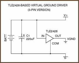
              The most elegant buffered virtual ground circuit is Texas Instruments? TLE2426. This part is called a ?rail splitter:? it splits a single supply in two, so you have two ?voltage rails? plus ground. It?s basically a glorified voltage divider, so it replaces the resistors in the simple resistor-divider power supply: you apply a voltage between its IN and COM pins, and it puts out ? that on the OUT pin. Unlike a simple resistor divider, though, it has some buffering circuitry inside so it doesn?t become unbalanced. (Oh, there may be a tenth of a volt of error or so, but that?s a small matter.) Here?s the modified power circuit:

              - วงจรTLE2426แบบ3ขา (ตัวถังTO-92)


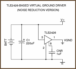
              - วงจรTLE2426แบบ8ขา (ตัวถังSO-8) (มีตัวช่วยเรื่องคุณภาพไฟเอ้าท์พุทดีกว่าแบบTO-92)


              The first schematic shows the simple 3-pin package, and the second shows the circuit for the 8-pin versions which have a noise reduction pin. The latter has slightly better performance.

              Notice that there is just one capacitor across the battery instead of a cap between each rail and virtual ground as in the resistor divider supply. In the resistor divider circuit, two capacitors are absolutely necessary to the success of the circuit. Below, I will talk about the advantages of using two caps like this in an active virtual ground circuit, as well as the disadvantages. For now, assume that it?s better to have just one before the active ?rail splitter.?

              The TLE2426 has an output current limit of between 20 to 40 mA, depending on operating conditions. When it goes into current limiting, its output goes to the negative rail, which would make for a massive shift in the virtual ground point, so we cannot allow this to happen. A heavy headphone load could indeed exceed 20 mA, so putting caps on the ouptut of the TLE2426 saves the design. Although the TLE2426 has no effect at audio frequency, it still has benefits compared to a resistive voltage divider.


              --------------------------------------------------------


              วงจรVirtual Ground ที่น่าสนใจ

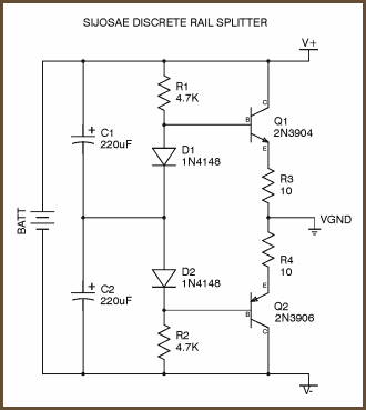
              Another option is to make a buffer from generic discrete components. This simple design comes from miniaturization guru Sijosae:


              The transistors can be most any complementary pair of small-signal transistors.

              The diodes are generic small-signal types.

              This circuit has better performance than a simple resistive divider virtual ground, and the parts cost is lower than for any other circuit mentioned here. It is, however, the least accurate of the buffered virtual ground circuits.
              Last edited by keang; 10 Mar 2012, 18:07:12.

              Comment


              • Originally posted by keang View Post
                ที่บอกว่าได้4โวลท์กว่าๆ นี่คุณวัดจุดไหนครับ (สายดำกับแดงของมิเตอร์)
                วัดที่ถ่านเลยครับ

                Originally posted by keang View Post
                TLE2426ตัวเดียวจ่ายกระแสได้น้อย เค้าก็เลยทำออปชั่นใส่ได้2ตัวเพื่อเพิ่มการจ่ายกระแสได้มากขึ้น
                ครับ ผมใส่ TLE2426 ไปอีกตัวแล้วครับ ตอนเปิดอาการแย่กว่าเดิมอีกครับ TT
                วัดไฟที่ถ่านได้ 2.4V

                Originally posted by keang View Post
                U4 ถ้าต่อจากไฟอแดปเตอร์ ก็เพื่อเรกกูเลเตอร์ระดับแรงดันไฟให้คงที่
                แต่ถ้าใส่อยู่ส่วนอื่น ผมเดาไม่ออกว่าเค้าใส่เพื่ออะไรเหมือนกัน
                ถ้าผมเข้าใจไม่ผิด U4 เอาไว้ต่อไฟจากอแดปเตอร์นั่นแหละครับ
                (ตัวที่ผมใช้เป็นรุ่นที่ชาร์จถ่านได้ครับ)

                Originally posted by keang View Post
                >> ตกลงแอมป์หูฟังตัวนี้ของคุณ ใช้งานได้ปรกติ หรือ ใช้งานไม่ได้ครับ <<
                ใช้ไม่ได้ครับ เสียงแทบไม่ออกเลยครับ พอเร่งให้สุด ก็เป็นเสียงซ่าๆครับ

                Originally posted by keang View Post
                The most elegant buffered virtual ground circuit is Texas Instruments? TLE2426. This part is called a ?rail splitter:? it splits a single supply in two, so you have two ?voltage rails? plus ground. It?s basically a glorified voltage divider, so it replaces the resistors in the simple resistor-divider power supply: you apply a voltage between its IN and COM pins, and it puts out ? that on the OUT pin. Unlike a simple resistor divider, though, it has some buffering circuitry inside so it doesn?t become unbalanced. (Oh, there may be a tenth of a volt of error or so, but that?s a small matter.) Here?s the modified power circuit:

                - วงจรTLE2426แบบ3ขา (ตัวถังTO-92)


                - วงจรTLE2426แบบ8ขา (ตัวถังSO-8) (มีตัวช่วยเรื่องคุณภาพไฟเอ้าท์พุทดีกว่าแบบTO-92)


                The first schematic shows the simple 3-pin package, and the second shows the circuit for the 8-pin versions which have a noise reduction pin. The latter has slightly better performance.

                Notice that there is just one capacitor across the battery instead of a cap between each rail and virtual ground as in the resistor divider supply. In the resistor divider circuit, two capacitors are absolutely necessary to the success of the circuit. Below, I will talk about the advantages of using two caps like this in an active virtual ground circuit, as well as the disadvantages. For now, assume that it?s better to have just one before the active ?rail splitter.?

                The TLE2426 has an output current limit of between 20 to 40 mA, depending on operating conditions. When it goes into current limiting, its output goes to the negative rail, which would make for a massive shift in the virtual ground point, so we cannot allow this to happen. A heavy headphone load could indeed exceed 20 mA, so putting caps on the ouptut of the TLE2426 saves the design. Although the TLE2426 has no effect at audio frequency, it still has benefits compared to a resistive voltage divider.


                --------------------------------------------------------


                วงจรVirtual Ground ที่น่าสนใจ

                Another option is to make a buffer from generic discrete components. This simple design comes from miniaturization guru Sijosae:


                The transistors can be most any complementary pair of small-signal transistors.

                The diodes are generic small-signal types.

                This circuit has better performance than a simple resistive divider virtual ground, and the parts cost is lower than for any other circuit mentioned here. It is, however, the least accurate of the buffered virtual ground circuits.
                ขอบคุณสำหรับความรู้ดีๆครับ

                Comment


                • Originally posted by iPol2n
                  ใช้ไม่ได้ครับ เสียงแทบไม่ออกเลยครับ พอเร่งให้สุด ก็เป็นเสียงซ่าๆครับ
                  รับทราบครับ


                  Originally posted by keang
                  ที่บอกว่าได้4โวลท์กว่าๆ นี่คุณวัดจุดไหนครับ (สายดำกับแดงของมิเตอร์)
                  Originally posted by iPol2n
                  วัดที่ถ่านเลยครับ
                  ผมว่า ตัววงจรกินไฟเกินกำลังที่ถ่าน9โวลท์จ่ายได้น่ะ

                  เพราะ
                  - ไม่ใส่ไอซีออปแอมป์ วงจรจ่ายไฟได้ปรกติ
                  - ยิ่งใส่ตัวอะหลั่ยเพิ่ม ไฟยิ่งตกไปเรื่อย


                  Originally posted by iPol2n
                  ถ้าผมเข้าใจไม่ผิด U4 เอาไว้ต่อไฟจากอแดปเตอร์นั่นแหละครับ
                  (ตัวที่ผมใช้เป็นรุ่นที่ชาร์จถ่านได้ครับ)
                  ลองถอดU4พร้อมอะหลั่ยรอบตัวมันออกครับ แล้ววัดไฟทุกจุดดูอีกที

                  Comment


                  • ไดโอดกลับด้านรึเปล่า?
                    เทียบกับรูปในคู่มือ
                    คู่มือคลิ๊ก

                    Last edited by ManiacMaew; 10 Mar 2012, 20:11:59.

                    Comment


                    • ที่้เป็นรอบหลังนี่น่าจะปัญหาไดรฟ์เวอร์ครับตัวการด์ไม่เกี่ยวโดนรื้อฟรีเลย 55 มันไม่ใช่เครื่องผมด้วยเลยไม่ได้ทำอะไรมากตอนนี้กลับมาบ้านเน็ตไม่ค่อยมีเล่นครับ

                      ตอนวัดไฟไปจิ้มขา C ตรงไฟเข้า WM8775 ช๊อตกันเปิดเพลงอยู่เพลงดับเลย เสียงหายพอรีคอมแล้วเสียงมาค่อยโล่งอกหน่อย รู้สึกว่าเสียงมันเบาลง ผมคิดไปเองหรือเปล่านี่ เดี๋ยวพรุ่งนี้ทำใจได้จะวัดใหม่ตกใจหมดเลยครับ จำได้ที่เดียวตรงขาออก REG 5V ได้แค่ 4.9 เดี๋ยวจะมาเพื่มพร้อมรูปครับ

                      Comment


                      • Originally posted by ManiacMaew View Post
                        ไดโอดกลับทางรึเปล่า?
                        เทียบกับรูปในคู่มือ
                        คู่มือคลิ๊ก

                        แต่ที่ pcb มันเป็นอย่างนี้นะครับ ผมก็เลยต่อตามนั้นไป


                        เอ๊ะ หรือว่าผมเข้าใจผิด ?

                        Comment


                        • เขาให้schematicมารีเปล่า?

                          Comment


                          • Originally posted by ManiacMaew View Post
                            เขาให้schematicมารีเปล่า?
                            ไม่ได้ให้มาครับ

                            Comment


                            • ลองไล่วงจรแล้ววาดschematicกลับมาดู ลองไล่แค่ทางเดินไฟก่อนก็ได้
                              ถ้ามีschematicในมือ ต่อไปมีปัญหาจะซ่อมหรือจะดัดแปลงอะไรมันจะง่าย วงจรพวกนี้ไม่ได้ซับซ้อนมาก

                              Comment


                              • ไปเจอmanualจากหน้าไหนลิ้งค์ไหนครับ ผมเห็นแต่ที่เค้าโชว์หน้าเวป
                                ที่หน้าเวปก็เป็นpcbรุ่นเก่า เลย์เอ้าท์ไม่ตรงกัน

                                Comment

                                Working...
                                X