 Tweet
Tweet
ถ้าตามที่ได้คุยกันคือบวกจุดบานปลายแล้วไม่เกิน4000 ก็ลงมือไปเลยครับ
กลางกับแหลมที่ผมพอใจคือความสมดุลของปริมานเสียงครับ ถ้าเปลี่ยนอะหลั่ยแล้วมันช่วยเรื่องเนื้อที่ดี รายละเอียดดีขึ่นไปอีกก็ไม่มีปัญหาครับ
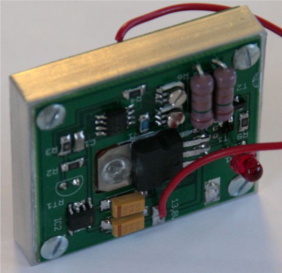
Cตัวที่ว่ามีคราบดำๆนี่ตรงจุดแถวไหนครับ
กลางกับแหลมที่ผมพอใจคือความสมดุลของปริมานเสียงครับ ถ้าเปลี่ยนอะหลั่ยแล้วมันช่วยเรื่องเนื้อที่ดี รายละเอียดดีขึ่นไปอีกก็ไม่มีปัญหาครับ
Cตัวที่ว่ามีคราบดำๆนี่ตรงจุดแถวไหนครับ


BLQK8pTW8Q~~_12.JPG)

OikY4ZQBMhHQ6I-dg~~_12.JPG)


Comment