Announcement

Collapse
No announcement yet.

โมให้ดีกันเยอะแล้ว มาม๊ะ....มาโมให้"เจ๊ง"กันดีกว่า

Collapse
X
 
  • Filter
  • Time
  • Show
Clear All
new posts

  • AVR ที่ใช้อยู่ตอนนี้ มีอาการเอ่อๆครับ ช่วยวิเคราะห์ให้หน่อยครับว่ามันเป็นที่อะไร จะเริ่มเช็คจากตรงไหนก่อนดี

    อาการคือ
    -กดปุ่มหน้าเครื่อง เลือกโหมด พวก CD , DVD , TV อะไรพวกนี้ มันจะไม่เปลี่ยนตามที่เราเลือกทันที ต้องกดย่ำ ถึงจะได้ (กดเลือก CD มันดันไปออก DVD ต้องกดไปเรื่อยๆ ถึงจะได้ )
    -กดปุ่มที่รีโมท เลือกโหมด พวก CD , DVD , TV อะไรพวกนี้ แทนที่จะกดทีเดียวแล้วเลือกเลย ต้องกด 2ครั้งตลอด ต่อการเปลียนโมท 1ครั้ง
    -กดปุ่มที่รีโมท ปุ่ม menu กดแล้ว มีไฟ status ที่รีโมทดิต แต่เครื่องไม่ตอบสนอง

    เครื่องเป็น Marantz sr4400 เก่าแล้วครับ ตอนนี้ยัง รู้ว่าเป็นที่ รีโมทหรือ เป็นที่เรื่อง เลยครับ

    Comment


    • แกะรีโมทออกมาล้างครับ
      แกะฝาบน-ล่าง จะเห็นpcbอยู่ข้างใน ล้างPCBด้วยแอลกอฮอร์ และล้างปุ่มกดที่เป็นยางด้วย

      เปิดฝาเครื่องavr
      เอาสเปรย์ล้างคอนแทค ฉีดไปที่ตัวสวิทช์ ขณะฉีดสเปรย์ก็กดสวิทช์ไปเรื่อยๆด้วย
      แต่ถ้าฉีดสเปรย์แล้วไม่มีไรดีขึ้น ต้องเปลี่ยนตัวสวิทช์แล้วละ ถอดของเก่าออกแล้วไปบ้านหม้อ
      Last edited by keang; 2 Mar 2012, 02:05:45.

      Comment


      • Originally posted by keang View Post
        แกะรีโมทออกมาล้างครับ
        แกะฝาบน-ล่าง จะเห็นpcbอยู่ข้างใน ล้างPCBด้วยแอลกอฮอร์ และล้างปุ่มกดที่เป็นยางด้วย

        เปิดฝาเครื่องavr
        เอาสเปรย์ล้างคอนแทค ฉีดไปที่ตัวสวิทช์ ขณะฉีดสเปรย์ก็กดสวิทช์ไปเรื่อยๆด้วย
        แต่ถ้าฉีดสเปรย์แล้วไม่มีไรดีขึ้น ต้องเปลี่ยนตัวสวิทช์แล้วละ ถอดของเก่าออกแล้วไปบ้านหม้อ
        รีโมท ล้างด้วยแอลกอฮอร์ แล้วครับ แต่ ที่คัวเครื่อง ยังไม่ล้าง พรุ้งนี้ว่าจะไปซื้อสเปรย์ล้างคอนแทค แล้วมาลองใหม่ครับ

        ถ้าหากไม่หายแล้ว ต้องเปลี่ยนปุ่มกด จะเป็นไปได้มั้ยที่ปุ่มกด ช๊อต แล้วทำให้เอ่อ รวมถึงการกดรีโมท ด้วย

        ปล. ถ้าหากปุ่มกดช๊อต ผมก็แค่ต้องถอดปุ่มกด ออกทั้มหมดแล้วลองกดด้วยรีโมท จะได้มั้ยครับ

        Comment


        • กำลังฟังเพลินเลยเสียงไม่ออกซะงั้นโดนรื้อครับ เรื่องเสียงเดี๋ยวค่อยว่ากันแล้วกัน

          Comment


          • มีขายร้านไหนบ้างครับดู ES แล้วไม่มี แล้วใช้เบอร์ไหนแทนได้บ้างครับ
            12v to 18v dc converter
            สามารถใช้บริดจ์ไดโอด เหมือนกับ AC to dc converter ได้หรือป่าวครับ

            ---------------
            LT1170


            http://www.eleccircuit.com/12v-to-18...ter-by-lt1170/

            ---------------
            ดูไปแล้วอันนี้น่าจะง่ายกว่า
            12v to 18v dc converter
            ถ้าตามตัวนี้เราเปลี่ยนตรงไหนถึงจะได้โวลล์เพิ่มขึ้นครับ
            Last edited by tiger X-fi; 2 Mar 2012, 09:43:39.

            Comment


            • รูปวงจรที่คุณเสือโพส อันล่างไม่ใช่วงจร DC-DC Converter หรือ DC-DC Step-up Converter น่ะครับ
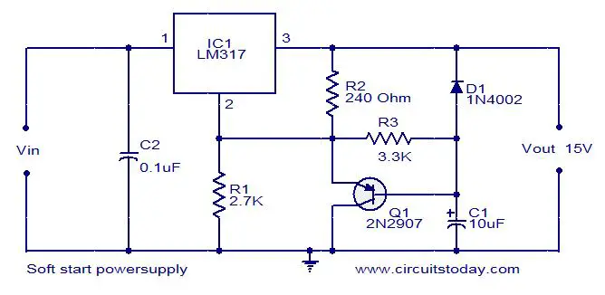
              เป็นวงจรเรกกูเลเตอร์ที่ใช้ไอซีเบอร์317 + ใส่วงจรหน่วงเวลาเพิ่มเข้าไป (เพิ่มหรือลดระยะเวลาที่ค่าC1)
              ปรับแต่งโวลท์เตจเอ้าท์พุท ก็ปรับจากค่าของR1กับR2


              > Soft start Power supply
              Description
              Here is the circuit diagram of a simple soft start power supply using the well known voltage regulator IC LM317.Here the IC is wired in soft start mode in which the output of the IC gradually increases to the desired output voltage .When the input voltage is given to the IC , the capacitor C1 starts to charge and the current from the adjust pin (pin2) of the IC increases.The output voltage of the IC at any time is proportional to this adjust current(I adj).So the output of the IC slowly increases from 0 to 15V which is set output voltage here.


              Notes
              - The circuit must be assembled on a good quality PCB
              - LM 317 can deliver only up to 1A 0f current
              - The input voltage must be few volts higher than the desired output voltage
              - Here the input voltage can be 18 or 20V DC
              - Capacitor C2 must be rated at least 30V


              -------------------------------------------------------


              > A step-up converter (18V @3A) by IC 555

              This is a power source that creates a DC voltage higher than the voltage feeding the it. It might be used to power your laptop (+18V) from a car battery (12V ~ 13.8V). It is built using very ordinary parts that should be readily available. Here are some specs:
              - Input voltage 9V ~ 15V
              - Output voltage 12V ~ 25V
              - Output current Max. 3A @18V
              - Switching frequency 20kHz ? 40kHz
              - Efficiency 65% ? 95%

              If you know these circuits, please skip the following. The circuit is a step-up converter, and it's workings can be explained by the main property of a coil: its inductance. Imagine a current flowing through a coil. The inductance will cause the current to continue running, even if the power supply that caused this current is taken away. The voltage across the coil will take any value required to keep the current running. This is why you can easily create sparks with a coil, a spark is simply a current flowing at a very high voltage.

              This circuit flips between two states: 'charging' the coil with current, and dumping this current into the output capacitor. The frequency at which this happens is so high that only a small ripple remains at the output capacitor (10,000uF). Here is the circuit.


              The 555, a timer circuit, generates pulses of specific width that control T1. T1 either grounds the coil, allowing current to build-up, or disconnects it, allowing current to flow through D1 into the buffer capacitor. The combination of R1 (10K) and the zener of 15V plus T2 is actually a simple voltage monitor. When the output voltage is higher than approx. 16.5V the output signal will drop low. As this signal is fed to the 555 RESET input, no pulses will be generated if the output voltage is above approx. 16.5V using a 15V zener. The 5V zener is necessary for proper startup of the circuit at powerup.

              Use a coil with 1 mm wire diameter, inductance approx. 200uH. T1 is a power darlington. A TIP141 works fine. A MOSFET would be better, use rdsON < 0.1 Ohm. T2 is an ordinary signal NPN, eg. BC547B. Use a power scottky diode (D1) for highest efficiency, but an ordinary silicon type will do. Take care: at 18V @3A quite a bit of power will be dissipated in the rectifier. Cool it. If you have the choice, use "low ESR" type of capacitors.

              So, what are the adjustable resistors for ? Well, although this principle works for whatever frequency, some frequencies do better. This is due to the fact that some power is lost by flipping states, some is lost by ohmic dissipation in the coil and more. All these mechanisms together case this converter to posses an 'optimal working point'. With this circuit, the point is characterized by two period lengths: charge_time and dump_time. These can be set independently by P1 and P2 respectively. At this optimum, power is converted at maximum efficiency (up to 95%).

              "Now, this is the catch", you may think, and you are right. It is not easy to trim this circuit to its optimum. Try the middle settings of the pots first. This should be a good starting point.

              P1 determines charge_time, P2 dump_time. This shouldn't be taken too long, as the coil will quickly 'saturate' causing a very large current to flow. Now slowly decrease both pots until the output current reaches its desired value. This is only step one. Step two involves finding an acceptable optimum. Keep adjusting the pots until you get the least input power while still maintaining the desired output voltage. I get an efficiency of approx. 75% at 30W using a schottky barrier rectifier.

              Be careful not to overheat T1 or D1, check their temperature regularly while adjusting.
              Last edited by keang; 2 Mar 2012, 12:07:07.

              Comment


              • ดูแล้วมึนครับพี่
                +12v 4จุด นั้นคือ +12v จุดเดียวใช่มั๊ยครับ
                สีเทาที่แปะ ที่ลายวงจร คือวงจรไม่ต่อกัน เช่น ขาTRI จะไม่ต่ออะไรเลย ต่อกับ ขาTHR เข้า C 0.1 ลงกราวน์
                P1 P2 มันคืออะไรครับ

                Comment


                • +12v 4จุด นั้นคือ +12v จุดเดียวใช่มั๊ยครับ
                  ใช่ ( ไฟอินพุท12vจ่ายให้วงจรนี้ )

                  สีเทาที่แปะ ที่ลายวงจร คือวงจรไม่ต่อกัน เช่น ขาTRI จะไม่ต่ออะไรเลย ต่อกับ ขาTHR เข้า C 0.1 ลงกราวน์
                  ใช่

                  P1 P2 มันคืออะไรครับ
                  - P1, P2 = ตัวต้านาทนแบบเกือกม้าปรับค่าได้ สำหรับปรับค่าไฟเอ้าท์พุทให้ได้ตามที่ต้องการ
                  - ไดโอด3ตัว เค้าแนะนำให้ใช้ไดโอดแบบschottky เช่น BYZ27, BYZ28 หรือ FE5A ก็ได้
                  - ขาเอ้าท์พุทของNE555จะจ่ายไฟออกเป็นPulse ความถี่40kHz เปรียบเสมือนเป็นไฟACจากหม้อแปลงไฟบ้าน

                  P1 determines charge_time, P2 dump_time. This shouldn't be taken too long, as the coil will uickly 'saturate' causing a very large current to flow. Now slowly decrease both pots until the output current reaches its desired value. This is only step one. Step two involves finding an acceptable optimum. Keep adjusting the pots until you get the least input power while still maintaining the desired output voltage. I get an efficiency of approx. 75% at 30W using a schottky barrier rectifier.


                  อันนี้ถือเป็นของแถม เพราะไม่ได้ถามมา แต่ถ้าทำจริงเดี๋ยวคงมาถามเพิ่มอยู่ดี
                  หน้าทรานซิสเตอร์ตัวขวาสุด จะมีตัวนึงสัญญลักษณ์คล้ายๆไดโอด มีกำกับค่า15vไว้ด้วย
                  ตัวนี้คือซีเนอร์ไดโอด เวลาซื้อก็บอกว่า ซีเนอร์ไดโอด15v 1วัตต์
                  ( จริงๆ0.5วัตต์ก็ใช้ได้ แต่ราคาแทบไม่ต่างกัน ก็เลยให้ใช้1วัตต์ไปดีกว่า )


                  --------------------------------------------------


                  การทำงานของตัววงจร
                  The 555, a timer circuit, generates pulses of specific width that control T1. T1 either grounds the coil, allowing current to build-up, or disconnects it, allowing current to flow through D1 into the buffer capacitor. The combination of R1 (10K) and the zener of 15V plus T2 is actually a simple voltage monitor. When the output voltage is higher than approx. 16.5V the output signal will drop low. As this signal is fed to the 555 RESET input, no pulses will be generated if the output voltage is above approx. 16.5V using a 15V zener. The 5V zener is necessary for proper startup of the circuit at powerup.
                  Last edited by keang; 2 Mar 2012, 13:52:22.

                  Comment


                  • พวกนี้หรือป่าว ครับ25K OHM TRIMMER


                    ทรานซิสเตอร์ มีตัวเดียวแถมไม่บอกเบอร์ด้วย นี่ใช้เบอร์อะไรครับ

                    Comment


                    • พวกนี้หรือป่าว ครับ25K OHM TRIMMER
                      ใช่
                      ใช้แบบ1รอบหรือ25รอบก็ได้ รอบมากก็ปรับได้ละเอียดขึ้น


                      ทรานซิสเตอร์ มีตัวเดียวแถมไม่บอกเบอร์ด้วย นี่ใช้เบอร์อะไรครับ
                      ทรานซิสเตอร์"ตัวซ้าย" = T1 = TIP141 ตัวนี้เป็นตัวกำหนดว่าจ่ายกระแสเอ้าท์พุทได้เท่าไหร่
                      ทรานซิสเตอร์"ตัวขวา" = T2 = BC547B

                      T1 is a power darlington. A TIP141 works fine. A MOSFET would be better, use rdsON < 0.1 Ohm. T2 is an ordinary signal NPN, eg. BC547B.

                      Comment


                      • Originally posted by coloner View Post
                        รีโมท ล้างด้วยแอลกอฮอร์ แล้วครับ แต่ ที่คัวเครื่อง ยังไม่ล้าง พรุ้งนี้ว่าจะไปซื้อสเปรย์ล้างคอนแทค แล้วมาลองใหม่ครับ

                        ถ้าหากไม่หายแล้ว ต้องเปลี่ยนปุ่มกด จะเป็นไปได้มั้ยที่ปุ่มกด ช๊อต แล้วทำให้เอ่อ รวมถึงการกดรีโมท ด้วย

                        ปล. ถ้าหากปุ่มกดช๊อต ผมก็แค่ต้องถอดปุ่มกด ออกทั้มหมดแล้วลองกดด้วยรีโมท จะได้มั้ยครับ
                        ล้างด้วย สเปรย์ล้างคอนแทค แล้วไม่หาย ตอนนี้ถอดปุ่มทั้งหมดออกหมดแล้ว
                        รีโหมดยังไม่หาย ต้องกด2ครั้งเลือกโหมดเหมื่อนเดิม และกดsetupไม่ได้
                        ตอนนี้ คิดว่า ถ้าไม่เป็นที่รีโมท ก็คงเป็นที่ชุดคำสั่ง

                        Comment


                        • ถ่ายรูปมาโพสให้ดูหน่อยครับ

                          Comment


                          • เอาปุ่มมาเปลียนแล้วครับ ซื้อของพานาโซนิก มาใส่
                            ปุ่มหน้าเครื่องปกติแล้วครับ เหลือแต่ทีรีโมท ยังเป็นเหมือนเดิมไม่เปลียนแปลง

                            เดียวมาอับรูปให้ครับ ตอนนี้ใช้งานในโทรศัพท์
                            อยากเห็นรูปตรงไหนเป็นพิเศษป่าวครับ จะได้เจาะจงถูก


                            รีโมทมีไฟสถานะบอกครับ เวลากดก็จะรู้ว่ากดติดหรือไม่ติด
                            ความผิดปกติคือ เวลาเลือกโหมด จะต้องกด 2ครั้ง
                            กดเลือก DTS อะไรพวกนั้นไม่ได้เลย ที่ทำได้ คือ เพิ่มลดเสียง ปกติ

                            ปล. คงไม่ได้อยู่ทำอีก 2-3 วัน ต้องออกเดินทางไปลำปางคืนนี้แล้วครับ
                            Last edited by coloner; 2 Mar 2012, 18:55:17.

                            Comment


                            • ตัวเครื่องปรกติแล้ว แต่ยังมีปัญหาที่รีโมท งั้นเอารูปภายในรีโมทมาโพสครับ

                              - ด้านใต้ปุ่มยางจะมีสีดำ จุดนี้ส่วนใหญ่จะเคลือบพวกกราไฟ
                              - pcbเฉพาะส่วนของลายทองแดงปุ่มกด

                              Comment


                              • Originally posted by nattapong29 View Post
                                กำลังฟังเพลินเลยเสียงไม่ออกซะงั้นโดนรื้อครับ เรื่องเสียงเดี๋ยวค่อยว่ากันแล้วกัน

                                ท่านนัฐ อยากลองฟัง onkyo SE-150PCI เปล่าครับ ผมให้ยืม

                                Comment

                                Working...
                                X