Announcement

Collapse
No announcement yet.

โมให้ดีกันเยอะแล้ว มาม๊ะ....มาโมให้"เจ๊ง"กันดีกว่า

Collapse
X
 
  • Filter
  • Time
  • Show
Clear All
new posts

  • ^^ อ้อ... ขอบคุณครับ NPE เอ ทำไมผมเห็นมัน 550:- ล่ะ สงสัยลืมดูน้ำหนัก อันนี้มัน 150g.

    -----------------
    ตามมาอยากรู้แหล่งขายในเมืองไทย ที่คุณkeang ถามด้วยคน

    พวก IC พวกนี้ส่วนใหญ่ผมก็สั่งเอาจากเมืองนอกหาง่ายดี แต่รวมๆแล้วแพงงหน่อย
    ส่วนมากก็สั่งเอาจาก Farnell(element14) หรือ RS น่ะครับ ค่าส่งถูก - ไม่มีค่าส่ง

    Comment


    • คุณdracoV มีข้อมูล "MCP100" กับ "MCP101" มีไรต่างกันบ้างครับ
      ผมดูดาต้าชีทแล้วไม่เจอรายละเอียดในส่วนนี้

      Comment


      • เป็น Voltage Supervisor และ Reset
        MCP100 -> Reset Active Low
        MCP101 -> Reset Active High
        ครับ

        Comment


        • Active low RESET pin(MCP100) or Active high RESET (MCP101)

          Comment


          • ขอบคุณครับ
            พอคุณdracoVกับคุณfanderfreeโพสบอก กลับไปดูดาต้าชีทอีกที ทีนี้ละเห็นเลย อยู่ที่หน้าแรกเลย

            Comment


            • เดี๋ยวไปลองหาคีมแบบนั้นมาติบบ้านครับ แล้วว่าจะไปหาซื้อหัวแร้งใหม่ด้วย ^^

              Comment


              • แปะ
                http://pinouts.ru/Slots/PCI_pinout.shtml
                ตัดต่อมาบ้างส่วนให้ดู
                เอาไว้ไล่ pin configของ pci


                PCI Universal Card 32/64 bit
                ----------------------------------------------------------------
                | PCI Component Side (side B) |
                | |
                | |
                | optional |
                | ____ mandatory 32-bit pins 64-bit pins _____|
                |___| |||||||--|||||||||||||||||--|||||||--||||||||||||||
                ^ ^ ^ ^ ^ ^ ^ ^
                b01 b11 b14 b49 b52 b62 b63 b94
                PCI 5V Card 32/64 bit
                | optional |
                | ____ mandatory 32-bit pins 64-bit pins _____|
                |___| ||||||||||||||||||||||||||--|||||||--||||||||||||||
                PCI 3.3V Card 32/64 bit
                | optional |
                | ____ mandatory 32-bit pins 64-bit pins _____|
                |___| |||||||--||||||||||||||||||||||||||--||||||||||||||

                _________

                +12v -12v มันก็มีอย่างล่ะเส้นแค่นั้นแหล่ะ
                Last edited by ManiacMaew; 16 Aug 2011, 22:02:43.

                Comment


                • ฝีมือกากๆอย่างผม อยากเปลี่ยน opamp sb0570 จะเจ๊งไหมครับ ไม่มี flux ด้วย

                  Comment


                  • ช่วยด้วยครับ อยู่ดี sb0570 ฟังไปเรื่อยมีเสียง แปะๆๆๆๆ ตลอดเลย เป็นนานๆครั้งน่ะครับ

                    Comment


                    • Originally posted by ManiacMaew
                      แปะ
                      http://pinouts.ru/Slots/PCI_pinout.shtml
                      ตัดต่อมาบ้างส่วนให้ดู
                      เอาไว้ไล่ pin configของ pci
                      +12v -12v มันก็มีอย่างล่ะเส้นแค่นั้นแหล่ะ


                      เราควรรู้ "PCI Bus Pinout" เพื่ออะไร ?
                      - การ์ดส่วนใหญ่ใช้ไฟเลี้ยงวงจรผ่านทางเมนบอร์ด โดยดึงไฟจากเมนบอร์ดผ่านทางอินเทอเฟสของตัวการ์ด
                      - เราศึกษาเส้นทางการจ่ายไฟของบัส เพื่อปรับปรุงประสิทธิภาพการจ่ายไฟให้ตัวการ์ดได้


                      หลายคนเคยใช้ไฟจากซัพพลายคอม เพื่อเป็นแหล่งจ่ายไฟให้ตัววงจรแอมป์หูฟัง หรือ จ่ายไฟให้ไอซีออปแอมป์ในซาวน์นการ์ด
                      ส่วนใหญ่จะเจอปัญหาเรื่องมีสัญญาณรบกวนปะปนมาในระบบไฟด้วย ก็ลองแก้กันด้วยวิธีต่างๆนาๆ ตามความถนัดของแต่ละคน
                      เท่าที่เห็นมา มีทั้งแบบดึงมาตรงๆจากหัวMolex, มีทั้งแบบใส่ไอซีเรกกูเลเตอร์เพิ่ม, มีทั้งแบบใส่ตัวเก็บประจุฟิลเตอร์ เพื่อหวังผลว่าจะช่วยลดสัญญาณรบกวนได้
                      แต่ผลที่ได้ก็จะบอกแบบเดียวกัน ยังคงมีสัญญาณรบกวนให้ได้ยิน แล้วก็คิดเหมารวมไปว่าไม่สามารถใช้ไฟจากซัพพลายคอมได้หรอก


                      " ถามใครว่าซัพพลายคอมเป็นยังงัย ร้อยทั้งร้อยก็บอกเหมือนๆกัน ซัพพลายคอมมีสัญญาณรบกวนเยอะ ไม่จำเป็นก็อย่าไปใช้มันเลย
                      บางคนก็เปลี่ยนไปใช้ถ่านใช้แบตเตอรี่แทน, บางคนก็หนีไปใช้ซัพพลายแบบสวิทชิ่งแทน(ก็ยังดึงไฟจากซัพพลายคอมอยู่ดี)

                      ถ้าใครเคยอ่านตามเวปDIY หรือ เวปโมเครื่องPlayerต่างๆ ทุกคนบอกซัพพลายสวิทชิ่งให้เสียงไม่ดี มีสัญญาณรบกวนปะปนสูงกว่าแบบLinear
                      หลายคนก็ถอดซัพพลายแบบสวิทชิ่งในเครื่องPlayerออก แล้วใส่แบบLinearเข้าไปแทนที่
                      "


                      แปลกแต่จริง , แปลกจริงหนอ
                      ถ้าหากคุณมองย้อนกลับไปสักนิด ทำไมซาวน์การ์ดต่างๆ ราคาไม่กี่ร้อยยันหลักหมื่น ทั้งหมดก็ใช้ไฟจากซัพพลายคอมทั้งนั้น
                      การ์ดพวกนี้ มีทั้งแบบ ใช้Passiveใช้ตัวอะหลั่ยRLCกรองความถี่, ใช้Active แบบใช้ไอซีเรกกูเลเตอร์ แบบใช้สวิทชิ่ง
                      ทำไมมันถึงไม่มีสัญญาณรบกวนให้ได้ยินแบบที่หลายๆคนทดลองทำกัน เพราะอะไรถึงเป็นเช่นนั้น ?

                      ผมว่าลองศึกษาระบบไฟของการ์ดต่างๆ เค้าใช้วิธีไหน เค้าใช้อะไร ถึงทำให้สัญญาณรบกวนมันต่ำลงจนไม่ได้ยินได้
                      ลองไล่วงจร เส้นทางของระบบไฟจากระบบบัสที่ส่งไปจ่ายให้การ์ดที่นำมาเสียบ ผมว่าน่าจะได้เห็นอะไรบางอย่างไม่มากก็น้อย

                      บางทีที่ยังไม่ได้ผลอย่างที่ตั้งใจ อาจเป็นเพราะการมองต้นตอของปัญหาคลาดเคลื่อนไป ทำให้ใช้การแก้ปัญหาผิดวิธีหรือเปล่า
                      Last edited by keang; 17 Aug 2011, 18:28:05.

                      Comment


                      • Originally posted by keang View Post

                        " ถามใครว่าซัพพลายคอมเป็นยังงัย ร้อยทั้งร้อยก็บอกเหมือนๆกัน ซัพพลายคอมมีสัญญาณรบกวนเยอะ ไม่จำเป็นก็อย่าไปใช้มันเลย
                        บางคนก็เปลี่ยนไปใช้ถ่านใช้แบตเตอรี่แทน, บางคนก็หนีไปใช้ซัพพลายแบบสวิทชิ่งแทน(ก็ยังดึงไฟจากซัพพลายคอมอยู่ดี)

                        ถ้าใครเคยอ่านตามเวปDIY หรือ เวปโมเครื่องPlayerต่างๆ ทุกคนบอกซัพพลายสวิทชิ่งให้เสียงไม่ดี มีสัญญาณรบกวนปะปนสูงกว่าแบบLinear
                        หลายคนก็ถอดซัพพลายแบบสวิทชิ่งในเครื่องPlayerออก แล้วใส่แบบLinearเข้าไปแทนที่
                        "
                        ผมมองต่างจากพี่โก้
                        มั่นใจแล้วหรือว่าสัญญาณรบกวนมันมาจากระบบไฟ
                        บางทีมันอาจมาจากส่วนอื่นก็ได้เช่นระบบกราวน์

                        ไม่รู้ว่าจำแอมป์ผมที่ใส่สไปค์ได้หรือป่าว
                        แค่ใส่สไปค์4 ตัว ใต้ฐานแอมป์ ทำให้เกิดเสียง ฮัมที่ลำโพง(เล็กๆ แต่ได้ยิน)
                        ต้องลาก GND ไปต่อสไปค์ทุกตัวถึงจะหาย
                        ที่สำคัญที่สุด....มันไม่ได้เกี่ยวอะไรกับวงจรเลย...กับสร้างปัญหาได้

                        Comment


                        • ปัญหาอาจจะลากยาวไประบบกราวน์ดด้วยน่ะ
                          ไม่เคยนั่งไล่ว่าเขาทำกราวน์ ไอโซเลชั่นไว้รึเปล่า

                          _______

                          conceptผมตอนทำซาวน์การ์ดให้ต่อไฟเพิ่ม ไม่ใช้เรื่องว่า "Psuสวิทชิ่งมันไม่ดี" แต่เป็นเรื่องว่าเฟสจ่ายไฟมันใช้ร่วมกันกับหลายอย่างในคอม ทำให้กวนกันข้ามระบบ
                          แยกทางเดินไฟไปไว้ให้ห่.างๆกันเลยแต่แรกน่าจะดีกว่า (ไปแยกกันที่รางปลั้กไฟหรือเต้าเสียบของไฟบ้านกันเลยดีกว่า)

                          ลดside effectทางเสียงจากการผ่านลายทองแดง-อะไหล่บนเมนบอร์ดและpsuมาอีก

                          จะว่าไปก็ลืมเทสback ground noiseก่อนแก้ ต่อไฟเพิ่มแหะ
                          Last edited by ManiacMaew; 17 Aug 2011, 16:21:02.

                          Comment


                          • เครดิต > pinouts.ru , interfacebus.com


                            USB interface description
                            USB (Universal Serial Bus) designed to connect peripherals such as mouses, keyboards, scanners, digital cameras, printers, hard disks, and networking components to PC. It has become the standard connection method for scanners, digital cameras and for some printers. Complete pinout.

                            Universal Serial Bus (USB) is a specification to establish communication between devices and a host controller (usually personal computers). An USB system consists of a host controller and multiple devices connected in a tree-like fashion using special hub devices. Hubs may be cascaded, up to 5 levels. Up to 127 devices may be connected to a single host controller. USB can connect computer peripherals such as mouses, keyboards, digital cameras, PDA, mobile phones, printers, personal media players, flash drives, GPS, Network Adapters, and external hard drives. For many of those devices, USB has become the standard connection method.

                            USB interface aimed to remove the need for adding expansion cards into the computer's PCI or PCI-Express bus, and improve plug-and-play capabilities by allowing devices to be hot swapped or added to the system without rebooting the computer.


                            The USB Pinout

                            Pin x of mini-USB connector may be not connected, connected to GND or used as attachment identification at some portable devices.

                            USB connectors
                            There are several types of USB connectors. The original USB specification detailed Standard-A and Standard-B plugs and receptacles. Nowdays there are 7 USB connectors known: Standard-A, Standard-B, Mini-A, Mini-B, Micro-A, Micro-AB, Micro-B.


                            USB pinout signals
                            USB is a serial bus. It uses 4 shielded wires: two for power (+5v & GND) and two for differential data signals (labelled as D+ and D- in pinout). NRZI (Non Return to Zero Invert) encoding scheme used to send data with a sync field to synchronise the host and receiver clocks. In USB data cable Data+ and Data- signals are transmitted on a twisted pair. No termination needed. Half-duplex differential signaling helps to combat the effects of electromagnetic noise on longer lines. Contrary to popular belief, D+ and D- operate together; they are not separate simplex connections.

                            Transmission at the High-Speed mode requires the addition of 45 ohm termination resistors between each data line and ground. Operation at Full-Speed mode is 2.8 volts [High] to 0.3 volts [Low]. Operation at High-Speed mode is at 400mV +/-10% [High] to 0V +/- 10mV {Low]. Cable impedance for both modes is 90 ohms +/- 15% (differential).


                            Four different (packet) protocols are used; Control, Interrupt, Isochronous and Bulk. Each exchange contains 3 packets; A token packet which holds the address, a data packet which holds the data, and a handshake packet which terminate the exchange.
                            NRZI produces a change in the signal indicating a logic zero, no change indicates a logic one. Bit stuffing is used with NRZI to stop the signal remaining in the steady state condition; if more then 6 ones are transmitted (no change in the signal) a zero is inserted to produce a transition. NRZI, with bit stuffing is self clocking, allowing the receiver to synchronize with the transmitter.


                            USB transfer modes
                            Univeral serial bus supports Control, Interrupt, Bulk and Isochronous transfer modes.

                            USB supports four data rates
                            - Low Speed (1.5 Mbit per second) that is mostly used for Human Input Devices (HID) such as keyboards, m, joysticks and often the buttons on higher speed devices such as printers or scanners.
                            - Full Speed (12 Mbit per second) which is widely supported by USB hubs, assumes that devices divide the USB bandwidth between them in a first-come first-serve basis - it's easy to run out of bandwidth with several devices.
                            - Hi-Speed (480 Mbit per second) was added in USB 2.0 specification. Not all USB 2.0 devices are Hi-Speed.
                            - SuperSpeed (USB 3.0) rate of 4800 Mbit/s (~572 MB/s).

                            A USB device must indicate its speed by pulling either the D+ or D- line high to 3.3 volts. These pull up resistors at the device end will also be used by the host or hub to detect the presence of a device connected to its port. Without a pull up resistor, USB assumes there is nothing connected to the bus. The new USB 3.0 standard, supports an extended speed of 4.8Gbit per second.

                            In order to help user to identify maximum speed of device, a USB device often specify its speed on its cover with one of USB special marketing logos.


                            USB powered devices
                            The USB connector provides a single 5 volt wire from which connected USB devices may power themselves. A given segment of the bus is specified to deliver up to 500 mA. This is often enough to power several devices, although this budget must be shared among all devices downstream of an unpowered hub. A bus-powered device may use as much of that power as allowed by the port it is plugged into.

                            Bus-powered hubs can continue to distribute the bus provided power to connected devices but the USB specification only allows for a single level of bus-powered devices from a bus-powered hub. This disallows connection of a bus-powered hub to another bus-powered hub. Many hubs include external power supplies which will power devices connected through them without taking power from the bus. Devices that need more than 500 mA or higher than 5 volts must provide their own power.

                            When USB devices (including hubs) are first connected they are interrogated by the host controller, which enquires of each their maximum power requirements. However, seems that any load connected to USB port may be treated by operating system as device. The host operating system typically keeps track of the power requirements of the USB network and may warn the computer's operator when a given segment requires more power than is available and may shut down devices in order to keep power consumption within the available resource.


                            USB power usage
                            - Bus-powered hubs : Draw Max 100 mA at power up and 500 mA normally.
                            - Self-powered hubs : Draw Max 100 mA, must supply 500 mA to each port.
                            - Low power, bus-powered functions : Draw Max 100 mA.
                            - High power, bus-powered functions : Self-powered hubs: Draw Max 100 mA, must supply 500 mA to each port.
                            - Self-powered functions : Draw Max 100 mA.
                            - Suspended device : Max 0.5 mA


                            USB voltage
                            Supplied voltage by a host or a powered hub ports is between 4.75 V and 5.25 V. Maximum voltage drop for bus-powered hubs is 0.35 V from its host or hub to the hubs output port. All hubs and functions must be able to send configuration data at 4.4 V, but only low-power functions need to be working at this voltage. Normal operational voltage for functions is minimum 4.75 V.


                            ------------------------------------------------------------------


                            USB cable

                            Very simple. Maximum length of cable is about 5 m for AWG20 and 0.8 m for AWG28 cable.


                            USB cable shielding
                            Shield should only be connected to Ground at the host. No device should connect Shield to Ground.


                            USB cable wires
                            Shielded :
                            Data: 28 AWG twisted
                            Power: 28 AWG - 20 AWG non-twisted

                            Non-shielded :
                            Data: 28 AWG non-twisted
                            Power: 28 AWG - 20 AWG non-twisted


                            USB Type-A, Type-B Connector


                            mini-USB A, mini-USB B Connector


                            USB D+ and D- are twisted in cable. Outer shell is made of copper braid and aluminum shield.

                            Colors do not mean anything in the wiring scheme. You can use any color wire to rig something. Just make sure the colors match from end to end. Using the de-facto color is for industry types only.

                            The maximum length of a standard USB cable (for USB 2.0 or earlier) is 5.0 metres (16.4 ft). The primary reason for this limit is the maximum allowed round-trip delay of about 1,500 ns. If USB host commands are unanswered by the USB device within the allowed time, the host considers the command lost.

                            The data cables for USB 1.x and USB 2.x use a twisted pair to reduce noise and crosstalk. USB 3.0 cables are more complex and employ shielding for some of the added data lines (2 pairs); a shield is added around the pair sketched.


                            ------------------------------------------------------------------


                            หน้า177 #3530

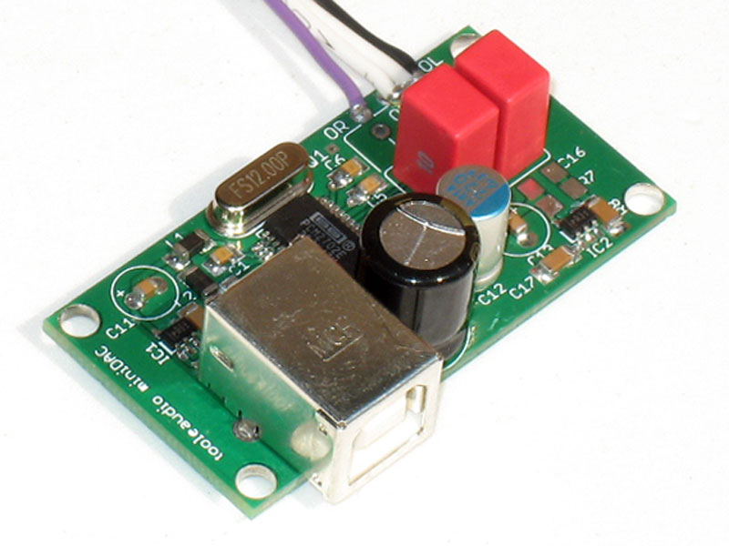
                            ก่อนหน้านี้ เคยโพสเรื่องให้ลองสังเกตุค่าตัวอะหลั่ย ในด้านตัวส่งต้นทางของUSB

                            Originally posted by keang
                            ช่วงนี้กำลังศึกษา เส้นทางส่ง>รับสัญญาณของพอร์ทUSB จะได้เข้าใจพฤติกรรมการทำงานของมันมากขึ้น
                            เอาการรับส่งข้อมูลพอร์ทUSB + เรื่องIsolated + ประสบการณ์เรื่องอะหลั่ยเรื่องสาย
                            วันไหนมีเวลาว่าง จะได้เอามาเป็นแนวทางสนุกกับสายUSB

                            ใครมีการ์ดUSB จะเป็นการ์ดแยกต่างหาก หรือ การ์ดเสริมของเมนบอร์ดรุ่นเก่าที่มีตัวอะหลั่ยด้วย ก็ได้
                            ที่อยากรู้ อยากได้ข้อมูล คือ อะหลั่ยในจุดนี้ เค้าใช้อะไรบ้าง ค่าเท่าไหร่


                            เหตุผลที่ให้ลองสังเกตุกัน เพราะ ข้อความข้างล่างนี้
                            speed by pulling either the D+ or D- line high to 3.3 volts. These pull up resistors at the device end will also be used by the host or hub to detect the presence of a device connected to its port. Without a pull up resistor, USB assumes there is nothing connected to the bus.


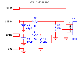
                            อันนี้รูปค่าตัวอะหลั่ย ในด้านตัวรับปลายทางของUSB ( R1, R2, R3 )


                            ตัวอย่าง : วงจรUSB Host (outputของด้านตัวส่ง)


                            ตัวอย่าง : วงจรUSB Filtering (inputของด้านตัวรับ)


                            ------------------------------------------------------------------


                            PCM2707 total = 30mA
                            VDD = 3.3V
                            VCCP = 3.3V

                            SRC4392 total = 125mA
                            VDD18 = 1.8V 58mA
                            VDD33 = 3.3V 15mA
                            VIO = 3.3V 44mA
                            VCC = 3.3V 8mA

                            WM8741 total = 100mA
                            AVDD = 5V 55mA
                            DVDD = 3.3V 45mA
                            Last edited by keang; 18 Aug 2011, 15:20:37.

                            Comment


                            • ขอปรึกษาหน่อยครับ พอดีลำโพงผมเสีย เบสไม่ดัง ผมลองไล่ดูแล้วเปลี่ยน opamp ของเบสเป็น LM49720 มันกลับมาเป็นปกติแต่ผมอยากทราบว่าถ้าเปลี่ยน อีก 3 ตัวจะมีผลต่อเสียงไหม เพราะในวงจรผมไม่เห็นมันต่อ มาจาก input ***ลำโพงผมยี่ห้อ leona G9

                              รูปก่อนเปลี่ยน Opamp ที่เสีย Opamp ผมเบอร์ BA4558


                              Comment


                              • มีผลครับ
                                แต่โดบรวมจะออกมาเป็นแบบไหน ถูกใจหรือไม่ถูกใจ คุ้มหรือไม่คุ้ม ต้องลองของจริงถึงจะรู้

                                ถ้ายังไม่แน่ใจ ลองเปลี่ยนทีละตัวก็ได้ครับ เริ่มจากIC704 > 3 > 2 > 1

                                Comment

                                Working...
                                X