Announcement

Collapse
No announcement yet.

D.I.Y.ตอน เครื่องขยายเสียง

Collapse
X
 
  • Filter
  • Time
  • Show
Clear All
new posts

  • NJM2396 > Data Sheet
    NJM2396F63 = V-out 6.3V (ไส้หลอด) : 6.3V 1.5A, TO-220F-4

    The NJM2396 is a low dropout voltage regulator with ON/OFF control. The output current is up to 1.5A and dropout voltage is 0.2Vtyp. at Io=0.5A. The NJM2396 is suitable for power module?TV?Display?car stereo and low power applications.

    - Low Dropout Voltage (VI-O=0.2V typ. at Io=0.5A)
    - Output Current (Io(max.)=1.5A)
    - ON/OFF Control
    - Internal Short Circuit Current Limit
    - Internal Overvoltage Protection
    - Internal Thermal Overload Protection
    - Bipolar Technology
    - Package Outline (TO-220F-4)

    ------------------------------------------------------------


    ------------------------------------------------------------


    Last edited by keang; 24 Apr 2014, 11:26:54.

    Comment


    • > Designing a Parafeed Headphone Amplifier


      ----------------------------------------

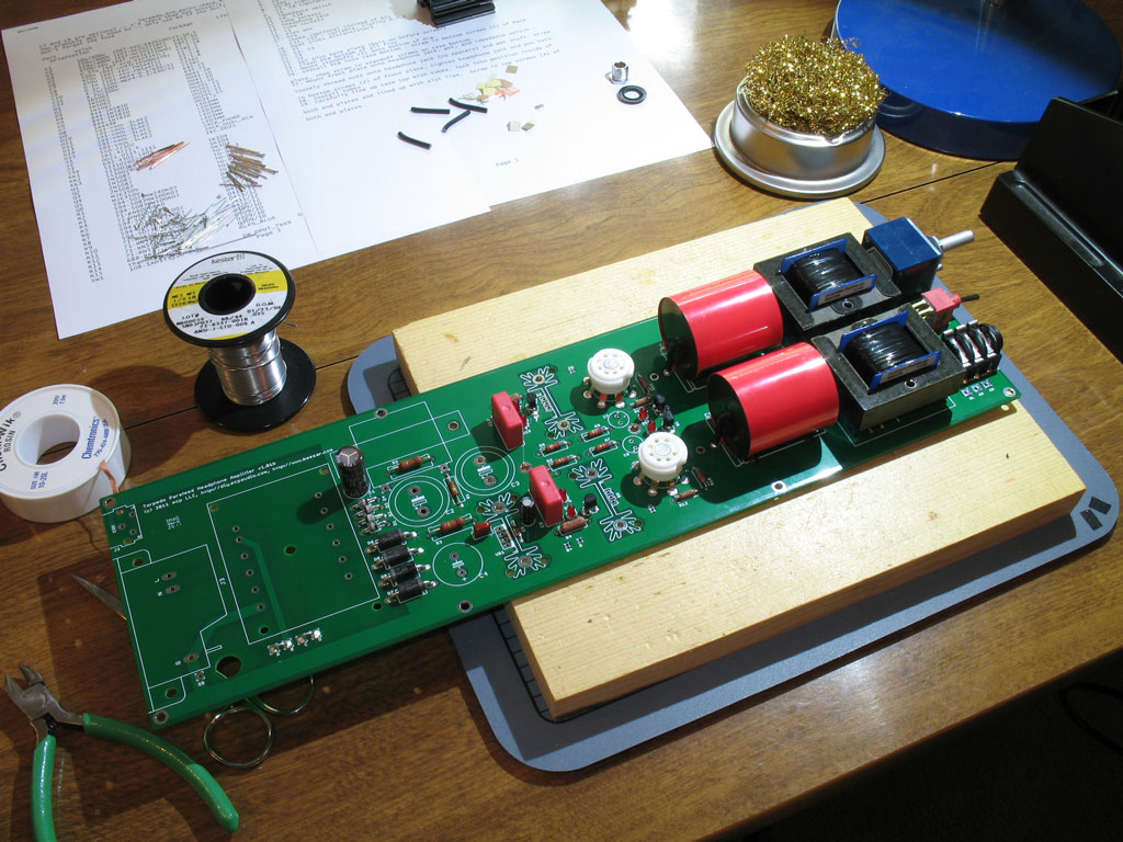
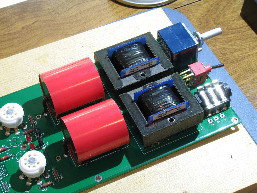
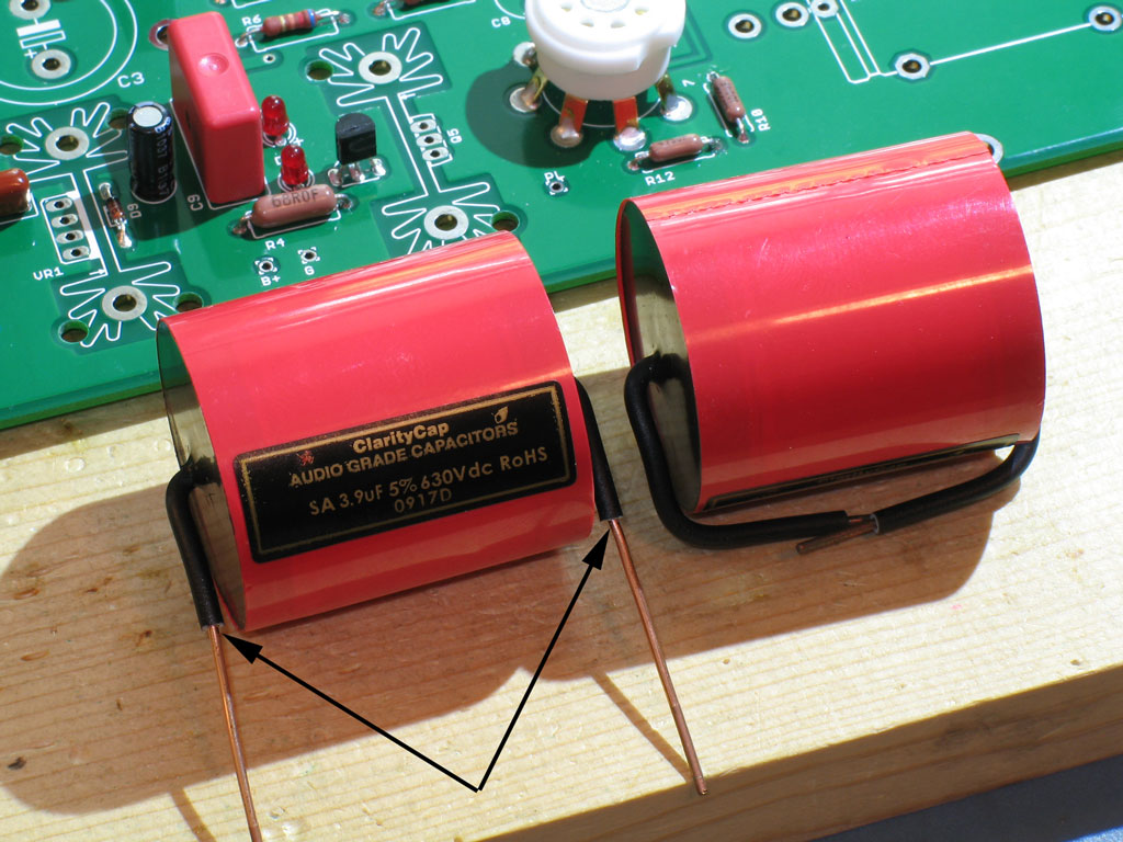
      > TORPEDO parafeed headphone amplifier


      uses a novel bi-polar transistor shunt regulator to provide a very low impedance and very linear bias.


      > Bill of Materials in PDF format
      Vacuum Tube : 6J6-A, 6J6-WA, 5844, 5964
      Q1, Q2, Q3, Q4 : 2N5087 PNP, TO-92
      Q5, Q6 : MJE350, 300V 0.5A PNP, TO-126
      D12, D14 : 1N5235B Zener diode, 6.8V
      D10, D11, D13, D15 : RED LED, 3mm - do not use other colors (Other LEDs may be used, but Forward Voltage is most important and optimum is around 1.8V)


      Last edited by keang; 24 Apr 2014, 15:17:21.

      Comment


      • Originally posted by keang View Post
        สงสัย สงสัย ใครมี1875 ลองใส่ไดโอด2ตัวนั้นเพิ่มเข้าไป ลองดูสิมีเสียงปุ๊กปั๊กตอนเปิด-ปิดเครื่องมั๊ย
        ขอลองหาดูก่อนน่ะ ว่าบอร์ดตัวทดลองอยู่ไหนยังใช้การได้มั้ย ถ้าได้อาจจะได้ทดลองแล้วมารายงานผลให้ฟังกัน
        ตัวใช้งานปัจจุบันคงไม่ถอดมาแก้ถ้าไม่มั่นใจว่าจะเปลี่ยนอะไรกับมัน เพราะมันรื้อยาก เหนื่อย

        Comment


        • แค่ผมรู้สึกว่า มันน่าจะมีผลไรตรงนี้ด้วย จะมากจะน้อยหรือไม่เกี่ยวเลย...ก็ไม่รู้เหมือนกัน
          ถ้ามันมีผล มันก็ไม่ได้แก้ปุ๊กปั๊กแบบหายขาดแน่นอน เพราะปัญหามันเกิดจากโครงสร้างภายในตัว1875เองด้วย

          Comment


          • > Modding the Melos SHA-1 Headphone Amplifier

            The Melos high voltage power supply consists of some solid state diodes and a p filter formed by two capacitors and a resistor. Now, I have no qualm with solid state diodes (I often use tube rectifiers, but this is primarily for the slow startup characteristics, not because I think they sound better ? they don?t). However, there are diodes, and then there are diodes. The Melos uses, so far as I can tell, some off the shelf cheapies that can withstand the voltage. The problem with this is that bad diodes impart switching noise into the power supply that does not sound good.


            The pi filter consists of a 470u cap, a 150R resistor, and a 100u cap. As can be seen, this arrangement results in both high ripple (over 9mV), as well as ripple containing all sorts of high frequency harmonics.


            The usual solution to this sort of thing is to add a choke. However, while adding a small choke reduces the ripple to a reasonable level, due to the capacitor arrangement, adding a choke here does not really do much to solve the sharp peaks.


            Moreover, also due in large part to the backwards arrangement of the caps (typically you want the caps to increase in a high voltage supply), the addition of the choke causes ringing.


            After futzing around with the original board, the solution here was to just tear the whole mess out and redo it. To this end, I first used super low switching noise avalanche diodes. These have about 25db less switching noise than standard rectifiers due to what are essentially built-in snubber caps. Additionally, I reduced the cap size (I find large caps in tube power supplies tend to make things muddy) and added a choke. I also added an extra filtering stage to make up for the smaller caps. While this is still not perfect, it is way better ? the ripple is smooth and small ? more than an order of magnitude smaller than it was before.


            ... and it doesn't ring.


            Last edited by keang; 24 Apr 2014, 15:13:43.

            Comment


            • > hifidiy : 47Labs Model 4706 Gaincard
              > diyAudio : internals 47 labs 4717 integrated
              > diy Audio Village : อีกสักครั้งกับ Shigaclone LM1875

              4717 Shigaraki


              ปริ๊นตัวจริง ดีไซน์เอนกประสงค์จริงๆ เนื้อทองแดงเป็นจุดพักhardwire-point2point
              Last edited by keang; 24 Apr 2014, 20:12:34.

              Comment


              • เก็บเล็กผสมน้อย
                > Power Supply Basics
                > Op-Amps - An Introduction
                > Hi-Fi Amplifiers for Beginners

                ----------------------------------------------
                Musical Fidelity A1

                - original circuit


                - Preamp replacement
                I decided to use the venerable NE5532 for the preamp. I know that it is an old device, but even today you have to spend a lot of money to improve on it. The biggest advantage is the excellent drive capability, meaning that with a non-inverting configuration, you can have very low-value components in the feedback path, minimising Johnson noise - remember, I was pretty paranoid about this issue at the time.

                You can try different op-amps in this circuit, but if you do, I'd recommend that you increase the value of R3 and R4 to reduce the loading on the op-amp, as many of the popular alternatives generate more distortion into loads less than about 2k?. You could simply increase them by a factor of 10 (to 6k8 and 2k2), but I'd recommend 3k and 1K. Good quality but affordable alternatives to the NE5532 include the OPA2604 and the OPA2134. I have tried the latter (with 3K and 1K gain setting resistors), and it worked fine... If trying anything more exotic, do take care with layout and decoupling, as parasitc oscillations are a very real possibility with some of the high-speed options.


                The first part of the circuit is an ultrasonic filter. Note that this is simply to avoid noise in the MHz range upsetting the op-amp*, and is not meant to be a bandwidth-setting component. The cut-off frequency varies with source impedance: -3dB @ 340kHz with 0? source impedance, and -3dB @ 190kHz with 1k source impedance. The amplifier bandwidth is set later by R4 and C5 on the main PCB.

                The volume control is a good-quality 10k log pot - deliberately low in value to minimise Johnson noise. Modern kit should be quite happy to drive this sort of load, although some exotic valve gear might not like it - in which case feel free to try a 50k instead... This pot is AC-coupled to the op-amp by a non-electrolytic capacitor. As above, the exact -3dB point is variable this time the position of the volume control will influence it. However, it is low enough not to be a problem and the LF cut-off is properly defined by C6 and C7 in the power amplifier.

                - Headphone amplifier
                This is based around an OPA2134 with a class B buffer formed by bipolar transistors. For most headphones of high to medium impedance, a single NE5532 normally has sufficient drive capability. However, adding the transistor buffer opens up the opamp choice by removing the need for good drive capability. The OPA2134 has a FET input stage, which means the DC offset of the stage is reduced to a few millivolts - this has the very welcome advantage of being able to DC-couple the output thus losing the large electrolytic capacitors that would otherwise be required.


                The buffer is included in the feedback loop and is very simple. While there are plenty of ways to improve it, check out on Doug Self's website for reasons why I didn't. That said, One refinement is the addition of the resistor from the opamp output to the buffer output - this enables the opamp to source current when the transistors aren't conducting. This is a very simple form of 'feed-forward' compensation - basically for very small output voltages (or high impedances) the opamp drives the load directly and avoids any cross-over distortion from the class-B buffer.

                ----------------------------------------------

                > A4 Power Amplifier (LM4780)

                Op-amp power supply

                The OPA2134 is powered from split 15 volt supplies. The unregulated supplies to the amplifier modules are around ?36V, which is on the limit for 7x15 regulators. So I chose a simple shunt power supply using two 12mA current sources and a pair of Zener diodes. The noise generated by the Zeners is filtered by a low-pass filter formed by a 15 ohm resistor and 47uF capacitor, turning over at around 200Hz. This frequency is comfortably low enough to ensure that the op-amps PSRR is sufficiently high to provide good ripple rejection. Finally, a low-ESR 1uF capacitor is connected between the power pins of the op-amp.

                This arrangement was arrived at after some experimentation - I found that using standard quality capacitors were best for the 47uF devices, and the 1uF between the supply pins, directly mounted at the IC, was best on its own. Additional ceramic or polyester capacitors didn't provide any additional benefit, either subjectively, or measured at the output or the IC supply pins.


                While it looks simple, this power supply is well-suited to this application. The current sources provide excellent isolation from the broadband noise and ripple on the unregulated supply rails. While the Zener diodes might not be the last word in DC precision, they are far better than required here.
                Last edited by keang; 24 Apr 2014, 22:00:56.

                Comment


                • มองๆดู ..เสียงตะกั่วมาเต็มๆ...

                  Comment


                  • ขาอะหลั่ย+สายไฟ เค้าต่อที่จุดเดียวกัน ระยะห่.างใกล้เคียงpoint2point
                    ถ้ากังวลเรื่องเอฟเฟคจากเสียงของตะกั่วก็ให้ใช้ตะกั่วในปริมาณน้อย หรือไม่งั้นก็เล่นกับเสียงของตะกั่วไปด้วยเลย

                    -- ตะกั่วเรายังเลือกหรือคอนโทรลเสียงได้ แต่ทองแดงของแผ่นปริ๊นเราเลือกหรือคอนโทรลเสียงไม่ได้ --

                    Comment


                    • Originally posted by tiger X-fi View Post

                      มองๆดู ..เสียงตะกั่วมาเต็มๆ...
                      ผมว่างานมันไม่ค่อยเรียบร้อยอ่ะ ไม่เก็บสายเลย

                      Comment


                      • Originally posted by carbon_za View Post
                        ผมว่างานมันไม่ค่อยเรียบร้อยอ่ะ ไม่เก็บสายเลย
                        ของผมยิ่ง hi-end สายขยุ้มๆยิ่งกว่านี้อีก....
                        Originally posted by keang View Post
                        ขาอะหลั่ย+สายไฟ เค้าต่อที่จุดเดียวกัน ระยะห่.างใกล้เคียงpoint2point
                        ถ้ากังวลเรื่องเอฟเฟคจากเสียงของตะกั่วก็ให้ใช้ตะกั่วในปริมาณน้อย หรือไม่งั้นก็เล่นกับเสียงของตะกั่วไปด้วยเลย

                        -- ตะกั่วเรายังเลือกหรือคอนโทรลเสียงได้ แต่ทองแดงของแผ่นปริ๊นเราเลือกหรือคอนโทรลเสียงไม่ได้ --
                        ขอบคุณครับพี่....ผมว่าเค้าตั้งใจใช้ตะกั่วจูนเสียงมั๊ง

                        Comment


                        • สายไฟ ผมว่าเค้าตั้งใจจัดสายนะ แต่จัดให้เป็นแบบที่เห็นนั่นละครับ
                          ... ลองสังเกตุ สายที่ระโยงระยาง ในแต่ละส่วน เช่น แผ่นปริ๊นสวิทช์/วอลลุ่มหน้าเครื่องไปที่แจ็คrcaหลังเครื่อง ...


                          ลองง่ายๆด้วยตัวเอง
                          - ลองฟังเสียงเทียบ ระหว่าง ใส่ท่องูหุ้มสายไฟ กับ ไม่ใส่
                          - ลองฟังเสียงเทียบ ระหว่าง สายถักตีเกลียว(หรือไขว้ก็ได้) กับ ไม่ถักไม่ไขว้ แต่ปล่อยสายกระจายตัวไม่ให้พันกันอีรุงตุงนัง

                          Comment


                          • Originally posted by keang View Post
                            ...
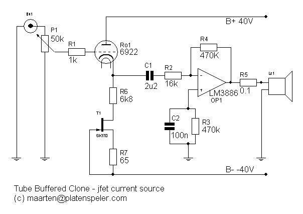
                            แอมป์741 เห็นมีไดโอด1N4148แชนแนลละ1ตัว คุณเสือลองปรึกษาคุณdracoV เปลี่ยน1N4148เป็นLEDแทนได้ป่าว

                            --------------------------

                            คิดว่าวงจรที่เล่นๆกันคงประมาณนี้มัง
                            ถ้าลักษณะการใช้ diode bias แบบนี้ จะใช้ LED แทนไม่ได้น่ะครับ เพราะเขาใช้ Forward voltage ของ diode ที่~0.6-0.7V
                            มา bias transistor แบบ BJT ที่ก็มี Vbe junction ที่~0.6-0.7V เหมือนๆกัน เพราะงั้นเวลา bias แล้วก็จะได้ output ที่ emitter มี dc component ใกล้ๆ 0V น่ะครับ

                            กรณีจะใช้ LED ก็มีข้อจำกัดคือ
                            - Forward voltage ของ LED ที่ใช้เข้ากับ Voltage ของส่วนที่ต้องการเอาไปใส่หรือไม่
                            - กระแสที่จะใช้ ก็ต้องไม่มากไม่น้อยไป ปกติคือ~1mA-30mA เป็นช่วงการทำงานของ LED

                            คร่าวๆน่ะครับ

                            Comment


                            • Originally posted by ManiacMaew View Post
                              รบกวนคุณdraoV
                              อธิบายตรงนี้เพิ่มนิดหนึ่ง เพื่อดัดแปลงเอาไปใช้กับวงจรอื่นด้วย

                              ------
                              editซ
                              รบกวนคุณdracoVอีกอย่าง
                              แนะนำanime seasonนี้ทีครับ ตอนนี้รู้สึกเปื่อยมาก ดูอะไรก็ไม่สนุก
                              55+
                              การใช้งาน Jfet ในลักษณะนี้จะมี impedance ขาเข้าสูงมาก ก็จะกระทบต่อสัญญาณน้อย
                              - Impedance แปรตามความถี่ เพราะงั้นในความเป็นจริงก็จะไม่คงที่นักสำหรับ impedance load ที่นำมาต่อ เช่น impedance ของลำโพง
                              ก็เลยมีการต่อ zobel มาช่วยคุม ที่นี้ zobel เองก็เป็น passive component (R, C) ก็จะมีการ drift ได้เหมือนกัน
                              การเอา CCS แบบ JFet มาต่อก็จะมาช่วยชดเชยการเปลี่ยนแปลงของ impedance ต่างๆได้ เนื่องจากตัวมันมีส่วนคงที่อยู่หลายๆส่วน
                              และเป็น active component

                              คร่าวๆน่ะครับ ลองทำความเข้าใจกับ JFet and/or CCS เพิ่มเติมครับ ทั้งการทำงานและใช้งาน
                              ถามอากู๋ดูได้

                              -------------------------
                              พูดถึงอากู๋ ตอนนี้ใครเป็นเหมือนผมไหม อะไรๆที่เกี่ยวกับ google นี่มันช้าไปหมดเลย
                              ไม่ว่าเว็บทั้งหลายที่ใช้ google api, google adservice, google..., youtube, etc...
                              เว็บ OCZ นี่ก็ด้วยเปิดแต่ละทีแต่ละหน้า ช้าหมดเลย ติด waiting google ทั้งหลายแหล่

                              อิอิ แถมเรื่องเม๊ะอีกหน่อย
                              ดูหนุกๆเอามันส์ๆ
                              - แนวๆ magic, superpower ก็ Mahouka
                              - แนวหนุกๆละกัน ไม่รู้เรียกแนวไรดี ก็ No Game No Life
                              เพิ่งมีเวลาไปโหลดๆมาดูก็หนุกดี

                              Comment


                              • Originally posted by keang View Post
                                สายไฟ ผมว่าเค้าตั้งใจจัดสายนะ แต่จัดให้เป็นแบบที่เห็นนั่นละครับ
                                ... ลองสังเกตุ สายที่ระโยงระยาง ในแต่ละส่วน เช่น แผ่นปริ๊นสวิทช์/วอลลุ่มหน้าเครื่องไปที่แจ็คrcaหลังเครื่อง ...


                                ลองง่ายๆด้วยตัวเอง
                                - ลองฟังเสียงเทียบ ระหว่าง ใส่ท่องูหุ้มสายไฟ กับ ไม่ใส่
                                - ลองฟังเสียงเทียบ ระหว่าง สายถักตีเกลียว(หรือไขว้ก็ได้) กับ ไม่ถักไม่ไขว้ แต่ปล่อยสายกระจายตัวไม่ให้พันกันอีรุงตุงนัง
                                เรื่องการถักสายตีเกลียว แม้กระทั่งผมทำเครื่องหลอด ก็ยังไม่คิดที่จะตีเกลียวสายสักครั้งเดียวเลยครับ.... น่าจะเป็นค่านิยมช่วงหนึ่งในอดีตที่ผ่านมา แต่ตอนนั้นผมยังไม่คลอดเลย

                                Comment

                                Working...
                                X