Announcement

Collapse
No announcement yet.

D.I.Y.ตอน เครื่องขยายเสียง

Collapse
X
 
  • Filter
  • Time
  • Show
Clear All
new posts

  • ขอบคุณครับ มีบริการเสริมแถมให้ด้วย

    - สูตรทำความสะอาดขาอุปกรณ์ด้วย"วิคซอล" คุณdracoVบอกว่า ห้ามใช้กับพวก"ตัวเซรามิค"
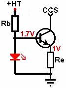
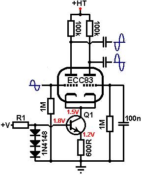
    - ใช้LEDแทนRแคโธด น่าสนใจมาก

    ---------------------------------

    หยิบจากหน้า38 - คุณเสือลงทุนวุ้ย แยกไดโอดกับฟิลเตอร์เลย
    Originally posted by tiger X-fi
    Last edited by keang; 19 Apr 2014, 14:48:07.

    Comment


    • Originally posted by keang View Post
      ไซส์เท่าR 1/8วัตต์(เล็กกว่าRN55อีกไซส์นึง) ยังได้เลยครับ : ฟีดแบค จะใช้โวลท์

      แอมป์741 เห็นมีไดโอด1N4148แชนแนลละ1ตัว คุณเสือลองปรึกษาคุณdracoV เปลี่ยน1N4148เป็นLEDแทนได้ป่าว

      --------------------------

      @แมว , เสือ
      ตอนนู้นมีคุยสุมหัวกันเรื่องปริ๊น1875 ตกลงได้ทำปริ๊นอันนั้นกันหรือเปล่าครับ พอจำได้ป่าวครับ...อยู่ทู้ไหนหน้าไหน
      น่าจะเป็นกระทู้ 40w ส่วนหน้าไหนจำไม่ไดแล้วครับ
      ---------
      ทำแล้วมาดูลายก็มึนเอง
      อนุกรมหม้อแปลง
      หรือไดโอด 2 ชุดฟิลเตอร์ชุดเดียวน่าจะดีกว่าครับพี่

      Originally posted by dracoV View Post
      อุปกรณ์บางอย่างโดนทินเนอร์ไม่ได้นะครับ
      หมายถึงยังไงครับพี่ ที่ถามเพราะปกติ
      ใช้พู่กัน จุ่มทินเนอร์ ล้างคราบฟลัคใต้ PCB ตลอด
      (ไม่โดนด้านบน)แบบนี้จะมีปัญหากับตัวอุปกรณ์หรือป่าว
      ว่าจะซื้อ โซเว่นมาล้าง...ไม่ได้ซื้อสักที
      Last edited by tiger X-fi; 19 Apr 2014, 15:34:26.

      Comment


      • > Heater / Filament Supplies

        DC heater supplies :
        Properly designed DC supplies do not cause hum since the stray current between filament and cathode is unchanging. However, DC supplies nearly always need to be voltage regulated or they can cause even more noise than an AC supply! (although simple rectification to DC does sometimes work).

        Simple, three-pin voltage regulators usually require an input voltage that is at least 2.5V above the output voltage in order to work. Most regulators cannot handle more than about 1A of current on their own, so it is quite common to operate the comparatively low current pre-amp valves from a simple regulator, and run the current-hungry power valves from an ordinary AC supply, since they are less prone to hum anyway. Higher-current regulators are available, however, at slightly higer cost. The regulator must always be fixed to a suitable heat sink.

        The simplest and most popular range of fixed-voltage regulators is the 78xx series. A 5V regulator can have its output raised to ~6.3V by elevating its ground terminal by 1.3V; the voltage drop across a pair of silicon diodes is almost perfect for this. Higher voltages could be obtained by using zeners instead, but the input voltage must always be at least 2.5V higher than the output. 6V regulators do exist, but are not as commonly available as the 5V versions.

        In the circuit below, the 7805 regulator can provide up to 1A on its own. If more current is required, the transistor can be added to provide up to 5A max (it too will need a heat sink). The 1uF capacitor must be positioned very close to the regulator. It does not have to be tantalum, a ceramic will do at a pinch. A normal 6.3V transformer winding will NOT provide sufficient voltage after rectification to power this circuit.


        Layout / lead dress :
        The lead dress of AC heater supplies is very important for noise reduction. The AC heater wires will have significant EM radiation and should therefore be routed well away from all signal wires, and are usually tucked into the corner of the chassis. The wires should either be made from twin cable (bell-wire) or better still, should be made by twisting the wires neatly and tightly together. In this way the wires are kept perfectly parallel and close to each other, which increases opposing field density and encourages the radiated fields to cancel out. Loosely twisted wires are no use at all.

        When heaters are wired in parallel; power valves should be first in the heater chain, followed by driver valves, with the input stage being last in the chain. This keeps current, and therefore radiated fields, at a minimum around the most sensitive stages of the amp. Even better is to run the pre-amp and power-amp sections from separate heater chains. If signal wires must cross the heater wires, they should do so at right angles.

        Valves in push-pull or in balanced stages (such as long tailed pairs using separate valves) should have their heaters wired in phase. Any noise induced will then be common mode and rejected by the stage (mostly). Valves in parallel single-ended stages should have their heaters wires out of phase for mutual cancellation. Using two different colours for the heater wires will make this easier.

        The common pre-amp valves (ECC83 / 12AX7 etc.) when run from a 6.3V supply, should be wired from one side only [see right], not by looping one heater wire all round the valve socket, which would create a hum loop and cause excessive interference noise (though many amp makers DO make this mistake and get away with it). The wire twisting must be kept very tight right up to the socket, where it matters most. Their pin arrangement is also deliberate, so that the main heater pins (4 and 5) can be orientated towards the chassis wall, allowing heater wires to be run along the wall away from any other sensitive signal wiring.


        A universal heater supply ?
        Everyone likes tube rolling, but it is somewhat dissapointing that the only valves which are compatible with the ECC83/12AX7 pin-out are the ECC81/12AT7, ECC82/12AU7 and 12AY7. But there are many other valves which conform to the more standard pin-out such as the ECC88/6DJ8, ECC85/6AQ8, 6N1P, 6N2P and other Russian types. Although we could provide a switch at every valve socket to select between the two pin-outs, it would be nice if we could just plug in any type without any changes. The following circuits are designed to allow this, but automatically detecting which type is inserted. All these circuits operate the ECC83 types from 12.6V. If an ECC88 type is plugged in, however, a zener diode is placed in series with the heater to limit the heater voltage to about 6.3V.

        Each circuit uses pin 9 on the valve socket as a control port. If an ECC83 is plugged in this pin goes positive, causing the SCR (U1 left-most circuit) or NPN transistor (Q1 middle circuit) to turn on, shorting out the zener. There is still a small drop across this device though, which is why the supply voltage is shown a little higher than 12.6V (it will probably be a little higher in this mode anyway, since an ECC83 only needs 150mA heater current).

        When an ECC88 type is plugged in, pin 9 is connected to nothing, so U1 or Q1 turns off, and current is steered into the zener diode, which drops roughly half the supply voltage across itself.

        For AC heater we simply use an NPN/PNP pair connected in parallel (Q1/Q2 in the right-most circuit). A triac or even an opto-triac could be used too. However, zener diodes can't be used in the same way for AC, so a resistor is used instead. Unfortunately this means that some of the Russian valve types (notably the 6N1P) can't be used, since they require up to 600mA current which causes too much drop across the resistor. Most European/American types and the 6N2P should be ok though. Another disadvantage of this design is that it is not balanced, so a humdinger pot will probably be needed to null any heater hum. None of these circuits have been tested yet, but are presented for enthusiastic builders to try out, so let me know if you do!


        ---------------------------------------

        > Constant Current Sinks

        The use of constant current sinks / sources (CCS's) in guitar amps is practically unheard of, whilst they are common place in hifi.

        CCS's have a variety of uses, most of which are employed to force other valves in the amp to operate in a more linear fashion, or to attain maximum levels of gain. Whilst they are not essential for guitar amps, they are certainly an option and provide a use for those odd valve types that don't seem to suit any other position in the circuit.

        The obvious disadvantages of CCS's is that they take up extra space, and if they are valve state they increase the heater current demand from the power transformer.

        They work by presenting a low (and ideally constant) impedance to DC, but a high impedance at AC. This gives the effect of using a very high resistance (to maximize gain for example) but without the drawback of a huge voltage drop or miniscule current performance.

        Just about any valve can be used as a CCS, but certain ones will lend themselves to certain circuits more than others. Tetrodes and pentodes make better CCS's than triodes, but require more components to set them up. Transistors can make almost perfect CCS's, but do not lend themselves to use with point-to-point wiring typical with valve amps.

        When designing a valve CCS, it is necessary to first know what current you actually want to achieve, and how much voltage you can allow across the valve (it is usual to allow at least 70V across the CCS since valves stop operating predictably at low anode voltages). It is then a case of selecting a valve whose characteristics are fairly linear under those conditions. Linearity in the CCS is important, as any variation in its operation will be passed on to the circuit it is controlling, and cause that to misbehave also.

        Once a suitable valve has been chosen, it is simply a matter of seeing what bias voltage is necessary to achieve your chosen current at your chosen anode voltage, and bias it accordingly. By leaving the cathode unbypassed the internal impedance of the valve increases due to internal feedback, and this is what forms the high AC load we want to achieve.

        Despite the many possible uses for a CCS, the two circuits most likely to benefit from using one are the cathode follower and the long tailed pair.

        Using a triode as a constant current sink :
        Suppose we wish to design a cathode follower with constant current sink. The HT is 295V and we decide to allow 90V across the CCS; this will be its quiescent anode voltage.

        This leaves 295 - 90 = 205V across the cathode follower which is fairly low for most triodes. The ECC82 (12AU7) however, performs well at lower-than-average voltages.
        We would like the cathode follower to be biased at exactly half HT for maximum headroom. Because we will force the current through the valve to be constant, we can simply draw a vertical line at a half HT and choose a bias point somewhere on it. We can then read off the constant current we need to obtain from the CCS.

        In this case a half HT is half the voltage across the cathode follower only; 205 / 2 = 102.5V. We draw a vertical line corresponding to this (of course, you could choose a different voltage if you would like the cathode follower to clip sooner):


        In this case the performance looks good at a bias voltage of -4V, giving an anode current of 3mA. This is the current we will need from the CCS.

        We now need to select a valve that shows reasonable linearity at an anode voltage of 90V and anode current of 3mA. The ECC88 would be ideal but is rather expensive. The ECC81 and ECC83 would be operating in grid current territory. The ECC82 actually still operates well under these conditions so we can use that (which is convenient since there are two triodes in each envelope).

        From the anode characteristics graph we can see that at Va = 90V, Ia = 3mA, the bias voltage is about -2.6V. Use Ohm's law to calculate the bias resistor for the CCS (Rk1):
        2.6 / 0.003 = 867 ohms.
        The nearest standard is 820R

        We also chose the bias point of the cathode follower to be -4V. We know 3mA must flow, so use Uhm's law to calculate its bias resistor (Rk2):
        4 / 0.003 = 1.3k
        The nearest standard is 1.2k, and normal rules apply for the grid-leak resistor (Rg2).
        (Of course, if the cathode follower is to be DC coupled then no bias resistor or grid leak is necessary. The grid can simply be set at four volts below the cathode which we have set to be 90V.)

        The CCS now forms the load for the cathode follower instead of a resistor. The value of this load (at AC only) is:
        r(ccs) = ra + (mu +1) * Rk
        (ra is found from the anode characteristics graph at the bias point of the CCS (Va = 90V, Ia = 3mA). in this case it is roughly 20k)
        r(css) = 20000 + (19 + 1) * 820
        = 36.4k.

        This is about twice as high as the value we would normally have used for the load on the cathode follower (see the section on the cathode follower for more theory), so its performance has been improved slightly but not impressively. We could have used a larger value for Rk1 to increase r(ccs), and set the grid bias on the CCS with a potential divider. You may also like to note that the circuit is very much like an SRPP, but we are feeding the upper grid rather than the lower.

        A higher mu / higher ra triode would also have made a better CCS, and a pentode has a very high ra and would make an excellent CCS, giving values of r(ccs) typically in the order of several Meg-ohms! However, since the performance of a cathode follower is excellent anyway, the use of a CCS is more novelty than necessity. The performance of the long tailed pair on the other hand, can be improved massively with the use of a CCS tail.

        Using a pentode as a constant current sink :
        In the diagram [below] 100V has been allowed across the pentode CCS and it is set to pass 2mA of constant current. Exactly the same design process applies to using a pentode as a CCS as for the triode previously, except that you must also choose and set the screen voltage. See the section on the small signal pentode for this. The load seen by the pentode CCS is very low; formed by the cathode resistor and cathode impedance of the 12AY7. The screen voltage can therefore be made the same as the anode voltage quite safely.


        Additionally, because the load on the pentode is so low, we needn't worry about noise from the pentode or zeners being amplified significantly.
        The ra of the pentode is so high compared to its cathode resistor that r(ccs) can be approximated as being equal to ra. In this case it is roughly 2Meg, so this circuit has the effect of using a 2Meg tail resistor on the long tailed pair, without the drawbacks! The performance of the long tailed pair becomes so perfect that its anode resistors can be made equal and excellent balance is ensured (see the sections on the long tailed pair for the rest of the circuit).

        Transistor constant current sink :
        There are many possible CCS circuits using transistors, many of which become quite extensive. The one provided here is the simplest, requiring one NPN transistor and a minimum of components.

        The red LED sets the base voltage at about 1.6V so the transistor is always 'on'. Rb is simply the current limiting resistor for the LED. Since it has to drop most of the HT at a few milliamps, it will usually need to be rated at 2W or more, unless there is a convenient, small positive supply voltage available. Alternatively, the base voltage could be acquired from the cathode of an LED biased gain stage.


        The base-emitter drop is about 0.6V, therefore the voltage across the emitter resistor (Re) must be at 1.6 - 0.6 = 1V. The emitter resistor sets the current since there must be 1V across it, use Ohm's law to find its value.

        For a constant current of 1mA :
        1 / 0.001 = 1k
        Note, this circuit may not work if Re is less than about 400 ohms because Vbe increases with current. If you need to sink more than about 2mA it is better to raise the base voltage by using an LED with a higher forward voltage, or zener diode.

        The AC impedance obtained will be roughly equal to:
        r(ccs) = Re * (2 * hfe) + 1 / hoe
        Where:
        Re = the emitter resistor
        hfe = rated current gain (the "2" comes from the fact that hfe tends to be about double its normal value when Ibe is less than about 10mA)
        hoe = ac impedance of the transistor
        But hoe is typically very small indeed, then to a close approximation;
        r(ccs) = Re * (2 * hfe)

        The diagram below illustrates how this CCS might be employed in the tail of a long tailed pair. Q1 may be any transistor, the higher the gain the better (the author used a ZTX615 with an hfe=170), and R1 should be sized to supply a couple of milliamps to the diodes. This particular circuit was tested and gave output signals that were less than 5% unbalanced, since it is equivalent to using an ordinary tail resistor of well over 100k!


        If used with a cathode follower, large signal voltages will be developed across the transistor so it will need to have a high Vce(max) rating, unless most of the load resistance is placed abode the transistor. Possible options are the MPSA42 (0.6W) useful for constant currents less than about 2mA, and the MJE340 (20W) that can handle just about anything. Both are rated at Vce(max) = 300V.
        Last edited by keang; 19 Apr 2014, 19:54:11.

        Comment


        • > Grid-Stoppers and Miller Capacitance

          A resistor is often placed in series with the signal before it reaches the grid of a valve. This is known as a 'grid-stopper' and serves several purposes.

          It is usual place the grid-leak resistor before the grid-stopper. This will increase the total grid-leak resistance so be sure not to exceed the maximum rated value. Adding it after the grid-stopper will create a potential divider that will attenuate the input signal slightly, which is usually avoided, although may be necessary in some cases.


          Frequency response and the Miller effect :
          Grid-stoppers can be used to control the high frequency roll-off response of amplfier stages.

          On the input of an amp its function is to 'stop' radio frequencies (all those above 20kHz) from reaching the grid and causing unwanted interference. While this wouldn't damage the circuit, inaudible RF interference can damage tweeters, and you certainly don't want to hear your local radio station playing through your amp!

          Wherever possible, the grid stopper should be soldered very close to, or directly onto the valve socket to maximise its effect, so that radio interference is less likely to be picked up on the wire between grid-stopper and valve grid.

          The grid-stopper attenuates the RF by forming a low-pass RC filter with the valve's 'dynamic input capacitance'. This is the combination of the valve's static inter-electrode capacitances, plus the Miller capacitance.

          The static inter-electrode capacitance is the product of all the internal capacitances within the valve, formed between the various metal parts. Miller capacitance is an effect produced within the valve (the Miller effect), such that the static grid-to-anode capacitance is actually multiplied by the gain of the stage. The static inter-electrode capacitances (those actually measured between valve pins), are quoted on the valve's data sheet, and the two most important are the grid-to-cathode (Cgk) and grid-to-anode capacitances (Cga), shown in red.
          (Cgk may not be quoted, in which case the "grid to all except anode" capacitance should be used instead.)


          The dynamic input capacitance (Cdyn) which you need to know when choosing a value for the grid stopper is:
          Cdyn = Cgk + (Cga * A)
          (Where: A = the voltage gain of the stage)

          Using a typical ECC83 triode with a bypassed cathode as an example:
          Cgk=1.6pF
          Cga=1.6pF
          A=60

          Cdyn = 1.6 + (1.6 * 60)
          = 97.6pF
          The actual wiring within the amplifier will also have 'stray' capacitance, so it is usual to add a few extra pico-Farads to our answer to allow for this, making about 100pF in total.

          To find a suitable value for the grid-stopper, simply apply the formula for a low-pass filter, where C is the dynamic input capacitance and f is the desired low roll-off frequency- in this case 20kHz:
          Rg = 1 / (2 * pi * f * C)
          Rg = 1 / (2 * pi * 20000 * (100 * 10-12))
          = 79.6k

          You will often see old amplifier designs using a 68k grid stopper. This will provide a roll-off of approximately 23kHz, which is close enough. However, the guitar itself also contributes a series resistance, that may range from a few kilo-ohms to several hundred kilo-ohms if the volume controls are turned down. This can easily cause treble frequenices to be rolled off, losing some of the high harmonics and 'chime' of the guitar sound. In practice it seems that in most cases the grid stopper can actually be made quite a bit smaller than 68k, and 10k to 33k will do, unless you happen to be playing nextdoor to a radio transmitter.

          It is worth noting that in pentodes Cag is very small, so the dynamic input capacitance can be assumed to be roughly equal to Cgk.


          Increasing Miller capacitance :
          A further problem with the usual approach is that it places a very large value resistor in the signal path, which introduces noise. This isn't a worry in later parts of the preamp, but at the input we want to keep it to the bare minimum.

          The grid stopper can be made smaller in value if the effective value of the input capacitance is made proportionately larger. This can be done by placing a capacitor between the anode and grid of the valve. This capacitor applies negative feedback of very high frequencies to the grid, and appears in parallel with the Miller capacitance, so its value is also multiplied by the gain of the stage, due to the Miller effect. Therefore the effective input capacitance is greatly increased and becomes equal to:
          Cin = Cgk + (Cga * A) + (Cf * A)
          Or: Cin = Cdyn + (Cf * A)

          To use the previous example, a roll-off of 20kHz is desired, but this time with a grid-stopper of just 10k. The necessary effective input capacitance required would be:
          Cin = 1 / (2 * pi * 20000 * 10000)
          = 796pF

          The value of the feedback capacitor would therefore be:
          Cf = (Cin - Cdyn) / A
          (where Cdyn is 100pF found earlier)
          = (796 - 100) / 60
          =11.6pF
          In this case the closest standard value would be 10pF, providing an acceptable roll-off of about 23kHz. The capacitor used should be of high quality so as not to introduce its own noise, and should have sufficient voltage tolerance to withstand the anode voltage. A close tolerance ceramic capacitor would suffice.

          For those afraid of the capacitor failing and placing a high voltage on your guitar strings, the capacitor could be placed between grid and cathode instead, although it will need to be a higher value since it won't be subject to the Miller effect. In this case:
          796 - 100 = 696pF
          The closest standard would be 680pF.


          The succeeding gain stages in an amplifier are normally enclosed within an earthed chassis where RF interference is unlikely to be picked up, therefore RF blocking is usually only used on the input where the guitar and guitar lead can act as antennae. However, if RF is getting into an amp somewhere, it may be necessary to add a grid stopper and/or feedback capacitor to the offending valve.

          Of course, we don't just have to limit RF. Any roll-off frequency can be chosen for this method, and it is often used to limit treble frequencies in bright amplifiers, and this is why you may see grid-stoppers in later stages within an amplifier.


          Other reasons for grid-stoppers :
          While the input of the amplifier will usually have a grid-stopper to remove radio interference, other stages in the amp- particularly the power valves- will often have grid-stoppers for different reasons.

          The first is that the actual wiring inside the amp will have stray inductances. In combination with the input capacitance of a valve, this will produce a resonant circuit which can cause parasitic oscillation, particularly in high gm valves like power valves. This is cured by damping the resonance with a grid-stopper, fitted directly to the valve socket if possible. Data sheets will usually list a recommended value of grid-stopper, and typical values are around 1k to 10k on power valves. If in doubt, make it bigger. Most small signal valves don't suffer from this condition, although the ECC88 is an example of one that does.

          The second reason is to limit grid current. In hifi this isn't such an important issue, but in a guitar amp the valves will often be driven well into grid-current territory. If left unchecked, this can cause the grid to exceed its ratings and be destroyed, although this is very rare.

          The second reason is to limit grid current. In hifi this isn't such an important issue, but in a guitar amp the valves will often be driven well into grid-current territory. If left unchecked, this can cause the grid to exceed its ratings and be destroyed, although this is very rare.

          The main reason for limiting grid-current is to reduce blocking distortion. By adding a grid-stopper, the input impedance of the stage cannot fall below the value of the grid-stopper. The maximum current that can flow in the grid is therefore limited, and the preceding stage cannot become so heavily loaded. By limiting the current we prevent the coupling capacitor from becoming fully charged during an overload, and therefore it can discharge faster once the overload has passed. Additionally, when current does start to flow during overload, the voltage drop across the grid-stopper will increase and so reduce the voltage on the grid countering, providing a voltage limiting effect as well as a current limiting one.

          For a good, modern design, all valves should have grid stoppers, even if it a small value of around 10k say. Values up to 1Meg are quite reasonable though, and are a powerful tool in tweaking the overdrive and treble characteristics of the amp. Except for the input stage, the stopper does not need to be connected directly to the valve socket. Stages enclosed within a feedback loop (usually the output stage) are even more suseptible to blocking distortion so using large grid-stoppers will be even more necessary for these.


          Screen-grid stoppers :
          The screen-grid on a power pentode should also have a grid-stopper to protect it from over dissipation when the valve is overdriven, which causes the screen-grid to draw more current. The voltage drop across the screen-stopper will reduce the screen voltage, hopefully saving the valve from destruction. The resistor is usually 1k in value and at least 1W, although higher wattages are more preferable.

          On ultra-linear power stages a grid-stopper on the screen-grid is not absolutely necessary, although for peace of mind it can be fitted. In hifi a 47R resistor is often used for this as it supposedly reduces distortion, and you sometimes see a similar resistor placed at the anode (anode-stopper) to quell parasitic oscillation or reduce distortion.

          Last edited by keang; 19 Apr 2014, 21:25:33.

          Comment


          • Transistor regulator
            In the simplest case a common collector transistor (emitter follower) is used with the base of the regulating transistor connected directly to the voltage reference:

            A simple transistor regulator will provide a relatively constant output voltage, Uout, for changes in the voltage of the power source, Uin, and for changes in load, RL, provided that Uin exceeds Uout by a sufficient margin, and that the power handling capacity of the transistor is not exceeded.

            The output voltage of the stabilizer is equal to the zener diode voltage less the base?emitter voltage of the transistor, UZ ? UBE, where UBE is usually about 0.7 V for a silicon transistor, depending on the load current. If the output voltage drops for any external reason, such as an increase in the current drawn by the load (causing a decrease in the Collector-Emitter junction voltage to obseve KVL), the transistor's base?emitter voltage (UBE) increases, turning the transistor on further and delivering more current to increase the load voltage again.

            Rv provides a bias current for both the zener diode and the transistor. The current in the diode is minimum when the load current is maximum. The circuit designer must choose a minimum voltage that can be tolerated across Rv, bearing in mind that the higher this voltage requirement is, the higher the required input voltage, Uin, and hence the lower the efficiency of the regulator. On the other hand, lower values of Rv lead to higher power dissipation in the diode and to inferior regulator characteristics.[3]

            R_v = \frac{V_{R min}}{I_{D min} + I_{L max}/(h_{FE} + 1)}\

            where VR min is the minimum voltage to be maintained across Rv
            ID min is the minimum current to be maintained through the zener diode
            IL max is the maximum design load current
            hFE is the forward current gain of the transistor, ICollector / IBase[3]

            http://en.wikipedia.org/wiki/Voltage...stor_regulator
            ------------
            แรงดันกระแส ของตัว Zd เป็น idle current (minimum current)
            ส่วนกระแสที่ดึงมาใช้ ไหลผ่าน ตัว Tr (ขายกระแส)
            ตัวTr ดรอปไฟประมาณ 0.6-0.7
            Rตัดศักย์ไฟ(v)-กระแส(A) เท่าที่ Zd รับได้
            -----------
            แล้ว Emitter-Base Voltage ปกติเห็นอยู่5 Vมันอะไรครับ
            ใช่โวลล์ตกคล่อม ระหว่าง ขา Emitterกับ ขา Base
            เช่น ไฟ เข้า13 ขา Base(ดรอป 0.6) ไฟออกขา Emitter 12.4
            ไฟตกคล่อมก็นิดเดียว
            -------
            หรือไฟออกขา Emitterไม่เกิน 5V
            เห็น 7812 + 2n3055 (Emitter-Base Voltage 7V)
            ก็ยังใช้ได้เลย
            http://www.arivigevano.net/Progetti/alimentatore.htm
            -------------
            หันมามอง เกี่ยวกับทางเดินสัญญาณ

            ก็จะเป็นลักษณะแบบนี้ใช่มั๊ยครับ
            bias Base
            ถ้ากำ หนดกระแส RL
            ก็เป็น bias Emitter
            ----------

            http://www.visionics.a.se/EDSpice-Si...-Follower.aspx
            Last edited by tiger X-fi; 20 Apr 2014, 04:05:04.

            Comment


            • "ไฟออกขาEไม่เกิน5V" คุณเสือหมายถึง วงจรที่เคยถามหรือเปล่า ที่ใช้ZD5.6V


              ถ้าใช่ ให้ดูศักย์ไฟ ที่ขาEเทียบกับB จะเห็นว่าต่างกันอยู่0.6V
              ส่วนเรื่องทรานซิสเตอร์เป็นสะพานไฟ(Vce)ได้กี่โวลท์ ให้ดูดาต้าชีท ว่ารับไฟได้เท่าไหร่ แต่ละเบอร์ก็จะต่างกัน

              2N3055 ระบุสเปค Veb 7V หมายถึง ศักย์ไฟระหว่าง2ขานี้ ห้ามเกิน7V
              Veb = the base for Transistor turn-on voltage
              Last edited by keang; 19 Apr 2014, 21:10:34.

              Comment


              • ู^
                เข้าใจแล้ว...ขอบคุณครับพี่

                Comment


                • @dracoV : หางานให้คุณdracoVเพิ่ม

                  #1 อยากได้แบบเนี๊ยะ ไปใส่ขาแคโธดในวงจรไฟ+-15V ก๊าบบบบ (ถ้าใส่วงจรไฟ+30Vได้ด้วยยิ่งดี) จะได้ครบเซ็ททั้งเพลททั้งแคโธดเลย


                  #2 เป็นความซนส่วนตัวครับ
                  > หยิบจากหน้า7 โพส#122

                  > LM723 datasheet
                  LM723 inside


                  LM723 equivalent circuit


                  LM723 pinout


                  1. ค่า Vsc = 0.66V มันมาจากไหน

                  2. จุดประสงค์ จะเอาไปลองเป็นชุดไฟเลี้ยงชุดAnalog ในวงจรDAC เพื่อเทียบกับพวกไอซีสำเร็จรูปเบอร์อื่นๆ กับ เพิ่มไฟเป็น6.3V เพื่อจ่ายไฟชุดไส้หลอด
                  2.1 คิดว่า ควรใช้ฐานวงจร #1หรือ#2 ครับ
                  2.2 เอ้าท์พุท5V ตัว723จ่ายได้MAXที่150mA : ถ้าจะเพิ่มกระแสเอ้าท์พุทเป็น 0.8-1.0A โดยใช้ทรานซิสเตอร์กับมอสเฟ็ทที่รับไฟถึง30Vขึ้นไป
                  อยากลองเทียบระหว่างทรานซิสเตอร์กับมอสเฟ็ท ขอคำแนะนำเรื่องวงจรด้วยครับ

                  วงจร #1 : เสริชเจอในเนท


                  วงจร #2 : เอามาจากดาต้าชีท
                  Last edited by keang; 19 Apr 2014, 21:32:39.

                  Comment


                  • Originally posted by keang View Post
                    --------------------------

                    @แมว , เสือ
                    ตอนนู้นมีคุยสุมหัวกันเรื่องปริ๊น1875 ตกลงได้ทำปริ๊นอันนั้นกันหรือเปล่าครับ พอจำได้ป่าวครับ...อยู่ทู้ไหนหน้าไหน

                    --------------------------
                    อันไหนหว่า แต่ผมวาดวงจร1875ไว้น่ะ คืออันที่เอามาทำใช้ปัจจุบัน ลายทองแดงเป็น non-invertธรรมดา แต่ไม่มีส่วนไว้ลงR-feedbackเพราะจะให้บัดกรีตรงที่ขา
                    เพื่อนู้นเพื่อนี้นิดหน่อย แต่เอามาใช้จริงผมทดลองไปมา แก้ลงอะไหล่เป็นแบบt-network

                    Comment


                    • ที่เคยคุยกันเรื่องเลย์เอ้าท์ลายปริ๊น : นานจัดจนลืม มีเอาไปทำใช้งานกันแล้วด้วย แต่ช่วงนั้นผมติดงานยาวเลยไม่ได้ร่วมทำด้วย

                      > D.I.Y.ตอน ต่อแอมป์ 40+40 w. ราคาไม่ถึงพัน - หน้า 187 #3734
                      รูปต้นฉบับที่ไปจิ๊กจากเวปนอกมาใช้อ้างอิง


                      เท่าที่ลองค้นกระทู้ดู เจอประมาณนี้

                      - LM1875 ของ คุณjinn
                      > D.I.Y.ตอน ต่อแอมป์ 40+40 w. ราคาไม่ถึงพัน - หน้า 187 #3724


                      > D.I.Y.ตอน ต่อแอมป์ 40+40 w. ราคาไม่ถึงพัน - หน้า 196 #3910


                      - LM3886 ของ คุณjinn
                      > D.I.Y.ตอน ต่อแอมป์ 40+40 w. ราคาไม่ถึงพัน - หน้า 187 #3724


                      - LM3875 ของ คุณManiacMaew / ขนาดไม่100% ต้องเอาไปปรับใหม่
                      > D.I.Y.ตอน ต่อแอมป์ 40+40 w. ราคาไม่ถึงพัน - หน้า 202 #4029


                      ถ้าขาดผลงานของใครไป ขอบอกว่าไม่เจตนานะครับ ก็ขอโทษล่วงหน้าไว้ด้วยครับ

                      --------------------------------------------


                      ตัวช่วยเรื่องกราวน์


                      STABILITY ก็อปจากdatasheet
                      The LM1875 is designed to be stable when operated at a closed-loop gain of 10 or greater, but, as with any other high-current amplifier, the LM1875 can be made to oscillate under certain conditions. These usually involve printed circuit board layout or output/input coupling.

                      Proper layout of the printed circuit board is very important. While the LM1875 will be stable when installed in a board similar to the ones shown in this data sheet, it is sometimes necessary to modify the layout somewhat to suit the physical requirements of a particular application. When designing a different layout, it is important to return the load ground, the output compensation ground, and the low level (feedback and input) grounds to the circuit board ground point through separate paths. Otherwise, large currents flowing along a ground conductor will generate voltages on the conductor which can effectively act as signals at the input, resulting in high frequency oscillation or excessive distortion. It is advisable to keep the output compensation components and the 0.1 uF supply decoupling capacitors as close as possible to the LM1875 to reduce the effects of PCB trace resistance and inductance. For the same reason, the ground return paths for these components should be as short as possible.

                      Occasionally, current in the output leads (which function as antennas) can be coupled through the air to the amplifier input, resulting in high-frequency oscillation. This normally happens when the source impedance is high or the input leads are long. The problem can be eliminated by placing a small capacitor (on the order of 50 pF to 500 pF) across the circuit input.

                      Most power amplifiers do not drive highly capacitive loads well, and the LM1875 is no exception. If the output of the LM1875 is connected directly to a capacitor with no series resistance, the square wave response will exhibit ringing if the capacitance is greater than about 0.1 uF. The amplifier can typically drive load capacitances up to 2 uF or so without oscillating, but this is not recommended. If highly capacitive loads are expected, a resistor (at least 1 ohm) should be placed in series with the output of the LM1875. A method commonly employed to protect amplifiers from low impedances at high frequencies is to couple to the load through a 10 ohm resistor in parallel with a 5 uH inductor.
                      Last edited by keang; 20 Apr 2014, 16:57:48.

                      Comment


                      • Originally posted by keang View Post
                        ที่เคยคุยกันเรื่องเลย์เอ้าท์ลายปริ๊น : นานจัดจนลืม มีเอาไปทำใช้งานกันแล้วด้วย แต่ช่วงนั้นผมติดงานยาวเลยไม่ได้ร่วมทำด้วย

                        > D.I.Y.ตอน ต่อแอมป์ 40+40 w. ราคาไม่ถึงพัน - หน้า 187 #3734
                        รูปต้นฉบับที่ไปจิ๊กจากเวปนอกมาใช้อ้างอิง


                        เท่าที่ลองค้นกระทู้ดู เจอประมาณนี้

                        - LM1875 ของ คุณjinn
                        > D.I.Y.ตอน ต่อแอมป์ 40+40 w. ราคาไม่ถึงพัน - หน้า 187 #3724


                        > D.I.Y.ตอน ต่อแอมป์ 40+40 w. ราคาไม่ถึงพัน - หน้า 196 #3910


                        - LM3886 ของ คุณjinn
                        > D.I.Y.ตอน ต่อแอมป์ 40+40 w. ราคาไม่ถึงพัน - หน้า 187 #3724


                        - LM3875 ของ คุณManiacMaew / ขนาดไม่100% ต้องเอาไปปรับใหม่
                        > D.I.Y.ตอน ต่อแอมป์ 40+40 w. ราคาไม่ถึงพัน - หน้า 202 #4029


                        ถ้าขาดผลงานของใครไป ขอบอกว่าไม่เจตนานะครับ ก็ขอโทษล่วงหน้าไว้ด้วยครับ

                        --------------------------------------------


                        ตัวช่วยเรื่องกราวน์


                        STABILITY ก็อปจากdatasheet
                        The LM1875 is designed to be stable when operated at a closed-loop gain of 10 or greater, but, as with any other high-current amplifier, the LM1875 can be made to oscillate under certain conditions. These usually involve printed circuit board layout or output/input coupling.

                        Proper layout of the printed circuit board is very important. While the LM1875 will be stable when installed in a board similar to the ones shown in this data sheet, it is sometimes necessary to modify the layout somewhat to suit the physical requirements of a particular application. When designing a different layout, it is important to return the load ground, the output compensation ground, and the low level (feedback and input) grounds to the circuit board ground point through separate paths. Otherwise, large currents flowing along a ground conductor will generate voltages on the conductor which can effectively act as signals at the input, resulting in high frequency oscillation or excessive distortion. It is advisable to keep the output compensation components and the 0.1 uF supply decoupling capacitors as close as possible to the LM1875 to reduce the effects of PCB trace resistance and inductance. For the same reason, the ground return paths for these components should be as short as possible.

                        Occasionally, current in the output leads (which function as antennas) can be coupled through the air to the amplifier input, resulting in high-frequency oscillation. This normally happens when the source impedance is high or the input leads are long. The problem can be eliminated by placing a small capacitor (on the order of 50 pF to 500 pF) across the circuit input.

                        Most power amplifiers do not drive highly capacitive loads well, and the LM1875 is no exception. If the output of the LM1875 is connected directly to a capacitor with no series resistance, the square wave response will exhibit ringing if the capacitance is greater than about 0.1 uF. The amplifier can typically drive load capacitances up to 2 uF or so without oscillating, but this is not recommended. If highly capacitive loads are expected, a resistor (at least 1 ohm) should be placed in series with the output of the LM1875. A method commonly employed to protect amplifiers from low impedances at high frequencies is to couple to the load through a 10 ohm resistor in parallel with a 5 uH inductor.
                        สำหรับ 1875 3875 C2 ไม่ต้องใส่หรอกครับเสี่ย R 1K แก้เป็น 680R ลงกราวด์เลยครับ ...ผมก็หัดทำแบบนี้ทุกตัวครับผม

                        Comment


                        • ได้ข้อมูลเพิ่มแล้ว ขอบคุณครับ : ไม่จำเป็นต้องใส่C2ก็ได้ = ต่อR3ลงกราวน์เลย สามารถลดค่าได้ถึง680โอห์ม

                          - คุณvachira ขอข้อมูลแนวเสียงของ 1875, 3875, 3886 หน่อยครับ : จะได้เป็นแนวทางการทำการเลือกใช้อะหลั่ยเพื่อชดเชย
                          - 3886 มีทริคหรือคำแนะนำไรบ้างครับ
                          Last edited by keang; 20 Apr 2014, 17:08:16.

                          Comment


                          • Originally posted by keang View Post
                            ได้ข้อมูลเพิ่มแล้ว ขอบคุณครับ : ไม่ต้องใส่C2 = ต่อR3ลงกราวน์เลย สามารถลดค่าได้ถึง680โอห์ม

                            คุณvachira ขอข้อมูลแนวเสียงของ 1875, 3875, 3886 หน่อยครับ
                            จะได้เป็นแนวทางการทำการเลือกใช้อะหลั่ยเพื่อชดเชย

                            ลืมไปอย่างครับเสี่ย C6 C7 จัด 1000uf Muse KZ นะครับ และไม่ต้อง Bicap จัดเต็มไปเลยครับ

                            ส่วนเรื่องหม้อแปลง หากต้องการข้อมูลผมยินดีเต็มที่ครับ แต่ขอคุยหลังไมค์ดีกว่าครับ เสี่ยมีเบอร์โทรไหม เด่วผมโทรหาก็ได้

                            Comment


                            • หม้อแปลง คงไม่ได้ใช้ครับ ทำเสร็จเดี๋ยวฝากเพื่อนๆในนี้เอาไปลองให้ครับ ถ้าไม่บึ้มก็ฝากเบิร์นไปเรื่อยๆก่อน
                              จริงๆ คือ ช่วงนี้มีเวลามาอ่านทู้บ่อยขึ้น แล้วมือมันคันยิบๆ ก็เลยอยากซุกซนบ้าง

                              บ้านผมมีปัญหาเรื่องตั้งลำโพงครับ พื้นที่ไม่สามารถวางได้แล้ว : ไม่ได้ใช้ชุดบ้านตั้งแต่ปี39แล้วมั้ง
                              เครื่องเก่าๆที่ผมเคยใช้ ยังต้องเอาไปฝากไว้บ้านเพื่อน ฝากเค้าเปิดให้เครื่องทำงานเป็นช่วงๆ เดือนสองเดือนครั้ง ไม่โดนไฟเลยเดี๋ยวเครื่อง/อะหลั่ยภายในเสื่อมหมด

                              ทุกวันนี้ ใช้แต่หูฟังอย่างเดียวเลย ว่าจะทำแอมป์หูฟังเล่นเหมือนกัน

                              ส่วนเรื่องคำแนะนำหม้อแปลง อันนี้น่าสนใจมากครับ เดี๋ยวผมขอเบอร์โทรทางหลังไมค์ครับ จะได้โทรหาได้

                              Comment


                              • Originally posted by keang View Post
                                หม้อแปลง คงไม่ได้ใช้ครับ ทำเสร็จเดี๋ยวฝากเพื่อนๆในนี้เอาไปลองให้ครับ ถ้าไม่บึ้มก็ฝากเบิร์นไปเรื่อยๆก่อน
                                จริงๆ คือ ช่วงนี้มีเวลามาอ่านทู้บ่อยขึ้น แล้วมือมันคันยิบๆ ก็เลยอยากซุกซนบ้าง

                                บ้านผมมีปัญหาเรื่องตั้งลำโพงครับ พื้นที่ไม่สามารถวางได้แล้ว : ไม่ได้ใช้ชุดบ้านตั้งแต่ปี39แล้วมั้ง
                                เครื่องเก่าๆที่ผมเคยใช้ ยังต้องเอาไปฝากไว้บ้านเพื่อน ฝากเค้าเปิดให้เครื่องทำงานเป็นช่วงๆ เดือนสองเดือนครั้ง ไม่โดนไฟเลยเดี๋ยวเครื่อง/อะหลั่ยภายในเสื่อมหมด

                                ทุกวันนี้ ใช้แต่หูฟังอย่างเดียวเลย ว่าจะทำแอมป์หูฟังเล่นเหมือนกัน

                                ส่วนเรื่องคำแนะนำหม้อแปลง อันนี้น่าสนใจมากครับ เดี๋ยวผมขอเบอร์โทรทางหลังไมค์ครับ จะได้โทรหาได้
                                อย่าเรียกผมท่านเลย ผมยังมือใหม่หัดขับอยู่เลยครับท่าน

                                Comment

                                Working...
                                X