Announcement

Collapse
No announcement yet.

[D.I.Y. + Project Log] ลองทำ DAC + Amplifier เล่นเองดีกว่า(?) ผมเรียกมันว่า FuWa :)

Collapse
X
 
  • Filter
  • Time
  • Show
Clear All
new posts

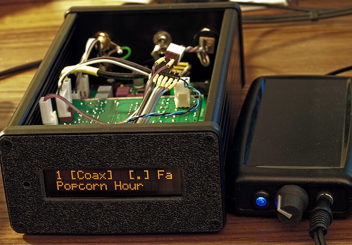
  • Ferrite ที่สายUSB ผมใส่กันสัญญาณกวนไว้หน่อย เพราะสายส่วนสั้น ปล่อยลอยshield ไม่ได้เชื่อมกับกราวด์
    ส่วนด้านยาวshieldเอามาเชื่อมกับกระป๋องไว้แล้ว แต่จริงๆแล้วก็จะไม่ใส่ก็ได้น่ะนะ

    ส่วนของสายpower ก็ใส่Ferrite กันEMI/RF เข้า/ออกมากวน เพราะตอนนี้บางทีถ้าต่อกับ Tube I/V
    ก็จะส่งเป็นไฟ AC มาด้วย

    Comment


    • ดีต่างกันเห็นได้ชัดมากครับ

      Comment


      • credit > making Digital Amp


        C-Media CM102 > datasheet


        Last edited by keang; 30 Mar 2012, 15:29:02.

        Comment


        • แจ่มเลยครับ Isolated GND เดี๋ยวว่างๆว่าจะลองทำดูบ้าง
          ตอนนี้ก็คิดว่าจะทำ DAC ที่ใช้ไฟจาก USB อย่างเดี๋ยวเล่นดูเหมือนกันครับว่าจะลอง
          หาทางให้ใช้ประสิทธิภาพจากไฟ VBUS ให้มากที่สุดดูครับ คิดว่าจะเอา
          MC34063 มาทำ DC-DC จ่ายให้ Op-AMP ดูครับ แปลง 5V -> +-9V ดู

          Comment


          • เรื่องโมไม่เกี่ยวกับเสียงนี้ผมก็เคยนะครับลองเอา Solen 1uF 400V ไปเปลี่ยน Cap ของพัดลมเหมือนกัน
            ของเดิมมันของถูก รู้สึกว่าลมพัดนิ่งขึ้นเนียนขึ้นลื่นใหลขึ้น 555 ไม่รู้คิดไปเองหรือเปล่า
            รู้สึกว่าเบอร์ 1 มันพัดแรงกว่าเดิมด้วยครับ

            Comment


            • ลืมแซว
              แหม สายพวกนี้พอมีอะไรเป็นบ้องๆ ใส่เข้าไป แล้วมันดูไฮโซ+ใช้เทคโนโลยีลึกล้ำ จากต่างดาว

              เอาไปตั้งชื่อหรูๆ ไปจดทะเบียนชื่อ แล้วเอาไปขายแพงๆ คงได้เส้นล่ะหลายพันได้

              Comment


              • แบบ JPS Labs ไงครับเอาป๋องไรติดๆเข้าไปเท่ๆ ขายที่เส้นล่ะครึ่งแสนถ้าไม่หูเทพจริงๆไม่รู้จะฟังออกหรือเปล่า

                อันนี้แถมครับเอา BSCH3V เขียนไว้เล่นๆ ง่ายๆสุดเลยใช้ไฟ VBUS อย่างเดี๋ยวสำหรับคนอยากทดลองสร้าง
                DAC เองครับ เอาไปต่อยอดกันดูนะครับ มีแค่ output กับช่อง spdif แบบง่ายๆแต่ไม่มี buffer ให้นะครับ
                ถ้าใช้สายยาวๆควรจะเอา 7404 มา buff ให้แรงขึ้นนะครับ
                Last edited by MONOLAB; 30 Mar 2012, 23:23:43.

                Comment


                • พี่dracoV. ไม่ลองเปลื่ยนเป็นกระป๋อง Heineken. ดูไหมครับบางทีเสียงมันจะได้ใสขึ้น ^ ^.
                  ช่วงนี้ไม่ว่างเลยยังไม่ได้ลอง 4780 ครับตอนนี้ก็อยู่ ตจว อยู่เลย

                  Comment


                  • อ๊ะ ว่าไม่ได้นะ 555+ ป๋องม่ายธรรมดานะเออ อลูฯอย่างหนา ข้างในฉาบทองเหลือง
                    เคลือบด้วย "Silver NANO" อีกชั้นนึงเชียวนา 555+
                    ...เพราะ... เป็นป๋องสเปรย์ Nivea for men SILVER PROTECT (โคนาว่า)มี Silver Ions
                    งั้นเดี๋ยวตั้งชื่อซะหน่อย ว่า สาย USB รุ่น Deo(dorizer)Blue ละกัน 555+

                    ใช้ป๋อง Heineken นี่จะเสียงใสขึ้นหรือจะลิ้นไก่สั้นขึ้นกันแน่นิ 555+
                    -------------------------

                    MC34063 นี่ก็ใช้ได้นะผมเคยเอามาทำstep-up สำหรับheaterใส้หลอด ตอนนั้นทำ hybrid amp.
                    ใช้ Switching power supply ของ PC ไม่มีไฟ 6.3V ก็ Step-up เอาจาก 5V เพราะไม่ได้ใช้งาน
                    ใช้แต่ 12V


                    ก็ โอเคนะใช้ได้ ไม่ร้อนด้วย แต่ตอนนี้ แอมป์ถูกแยกส่วนไปแล่ว เหลือแต่ตัว Step-up เก็บไว้
                    พร้อมกับ IC ที่เหลืออีกหลายตัว ทั้งแบบ DIP และ SMD ไม่รู้ซื้อมาทำไมตั้งหลายๆตัว(อีกแล้ว) 555+
                    เดี๋ยวต้องหาเรื่องใช้บ้างละ

                    อืม... ถ้าจะใช้ทำsupply ให้ op-amp นี่ MC34063 ความถี่มันอาจจะต่ำไปสักนิดนึง
                    คือสูงสุดได้แค่ประมาณ 100kHz +ต้องการวงจร/อุปกรณ์เสริมภายนอกเยอะนิด
                    ถ้ายังไม่ได้ซื้อ IC มาลอง ลองใช้ LT1372/LT1377 ดูครับความถี่ ~500k-1MHz

                    หรือถ้าอยากได้แบบใช้ง่ายๆ อุปกรณ์ภายนอกน้อยหน่อย ก็ลอง ICL7660S ได้ครับ
                    ตัวนี้ความถี่อาจจะต่ำหน่อย กระแสOutput น้อยนิดนึงที่~40mA MAX แต่ก็น่าจะพอสำหรับ Op-amp นะ
                    มันสามารถทำ boost และ Invert ได้ในตัวเดียว ประหยัดที่ทางและอุปกรณ์ไปได้เยอะเลย


                    ขอบคุณสำหรับวงจรPCM2706/2707ด้วยครับ เผื่อท่านใดสนใจได้เอาไปลองทำเล่นกันได้
                    Last edited by dracoV; 31 Mar 2012, 13:26:26.

                    Comment


                    • ขอบคุณนะครับสำหรับวงจร ICL7660S แจ่มดีครับทำ Invert ได้ในตัวเลยน่าจะเหมาะกับวงจรกินกระแสะน้อยๆ
                      ดีครับแต่ MC34063 ต้องมาพันแกนเอง
                      จะว่าไป MC34063 ผมก็ซื้อมาตุนไว้เพียบเหมือนกันแค่เอามาลองต่อทดลองทำ
                      DC-DC จ่าย Op-amp ดูเล่นๆรอบเดียวเองครับ ยังคิดไม่ออกว่าจะเอาไปทำไรต่อดี
                      แต่ดูแล้วน่าจะมี ประโยชน์ เลยขอซื้อเก็บไว้ก่อน 555 ที่ ES เคยของขาด รอบหนึ่ง แต่ตอนนี้ล็อตใหม่มาบาน

                      Comment


                      • A DIY PORTABLE HEADPHONE AMPLIFIER WITH USB-DAC

                        The amplification circuitry of this amp is build around an opamp. However, instead of the standard solution that uses a non-inverting opamp stage with a fixed amplification factor that is preceded by a potentiometer to attenuate the incoming signal, this design uses an inverting opamp stage with a variable gain factor. The gain factor is set by the potentiometer. There are some major advantages to this somewhat unconventional approach.

                        Very importantly background noise at low volume settings is strongly reduced because of the very low gain factor of the output stage. In a more conventional approach with an output stage with a fixed gain factor the noise of this output stage can become very dominant, especially when using high sensitive headphones.

                        Also feedback is stronger at lower..medium sound levels and thereby distortion is further reduced when compared to conventional approaches.

                        The voltages of the input stages in an inverting opamp setup are kept at ground potential and do not fluctuate. Thus influences of non-linear input capacities are strongly minimized. Inverting opamp stages normally sound better than non-inverting stages.

                        Of course there is also a drawback. The phase of the original input signal is inverted. However, since most people are unable to hear any difference between an inverted and a non-inverted signals this aspect is mainly of academic interest only.


                        The schematics of the design are shown in the picture above. The blue components are the one needed for the amplification circuitry and the power circuitry. The black components are needed if people are also interested in implementing the USB-DAC. The schematics show the LM6171 opamp but there are many other options possible, each having its own sonic signature.

                        Basically the left amplification channel only requires one single opamp IC1 and two resistors, R11 and the variable resistor represented by the 100 kOhm potentiometer Rpot. The amplification factor is equal to Rpot/R11.

                        C1 was added to improve stabilisation of the opamp. In principle it is not needed when using low-speed opamps but in combination with the LM6171 its use is mandatory to prevent oscillation of this extremely fast (100 MHz, 3600 V/usec slewrate) opamp. Even with slow opamps it never hurts to leave this capacitor in place, provided you use one of high quality (polystyrene or polypropylene are recommended!).

                        R9 helps to decouple the non-inverting input of the opamp from RF-noise on the signal ground and prevents fast opamps to work as a radio-receiver. Again, this is not necessary when using slower opamps but it never hurts to keep this resistor in place.

                        R13 and the switch S5 were added to be able to increase the gain factor when driving high-impedance headphones which need higher output voltages. When S5 is closed R13 is placed in parallel with R11, thus lowering the gain factor as set by Rpot/R11. The maximum amplification factor of the amplifier is 17 dB. This allows to drive inefficient, high impedance headphones even if a source with a low output voltage (portable) is used. However, if people only use high or medium efficient headphones and/or sources with a high output voltage (stationary CD-player) then it is recommended to use a potentiometer with a lower resistor value. This will simply improve volume control and prevent channel imbalances at very low sound levels (which are an inherent "property" of mechanical potentiometers).

                        R15 provides a low resistance DC-path for the input bias currents of the LM6171 and helps to reduce any offset at the output of the opamp. The input bias currents of the LM6171 are relatively high (bipolar inputs) when compared to most other opamps (having fet-inputs) and the only DC-path provided is through the potentiometer. At high gain factors, when the resistance value of the potentiometer is high, the product of high bias current and high resistor value results in a rather strong voltage offset. R15 is not required when using fet-opamps.

                        R17 connects the output of the opamp to the negative voltage rail and drives the output stage of the opamp into class-A operation. With some opamps this greatly improves sound quality but it also increases current consumption. The optimal resistor value strongly depends on the opamp model used and the supply voltage (as well as personal taste!). Trying is the only way to know.

                        R19 is only required when using fast opamps that don't like to drive high capacitive loads (headphone cables) and improves stability.

                        R1 and C3 form a low-pass filter that keeps RF-signals away from the inverting input of the opamp.

                        R5..R8 and C5..C9 (in combination with R1 and R2) form a crossfeed filter that can be activated with S1. If crossfeed is not required these components can be left out.

                        Power is supplied by a 9V battery or a 9 .. 28 Volts external powersupply. The power voltage is splitted by a TLE2426 rail-splitter to create positive and negative powerlines of 4,5 .. 14 Volts. It is not allowed to connect an external supply and a battery simultaneously. The amp is protected against reversed voltages by D3. The amp is switched ON/OFF by S2..

                        For people who also like to implement the USB-DAC please check the website of Texas-Instruments to download the data-sheet of the PCM2704. The function of the black components in the upper left side of the schematics will thus become apparent.

                        It is possible to connect the analog outputs of the PCM2704 to ground using 680 Ohm resistors. These drive the output stages of the PCM2704 into class-A and help to improve sound quality. You will not find an explicite place for them on the PCB but it is relatively easy to add them by hand.

                        Be aware, soldering the PCM2704 is extremely complicated as this chip comes in a 28-pin SSOP package! It requires a very experienced hand and proper soldering tools to do the job! Implementing the USB-DAC is not a job for beginners!!!

                        The circuitry around the LM2662 was added to create a negative 5V powerline from the positive 5V USB-powerline to power the amplification section so the amp can be used without battery or external powersupply when connected to USB.


                        Last edited by keang; 1 Apr 2012, 12:27:46.

                        Comment


                        • credit : linuxworks @ headfi.org
                          > IC: DIY spdif switcher


                          Comment


                          • @keang
                            มีใช้ MC14051กับ SPDIF Selector ด้วย
                            ตัวเดียวกับที่ผมใช้ใน SPDIF buffer/selector type 2 ที่ส่งวงจรไปให้น่ะครับ

                            ที่ผมใช้คือ MAX4617CPE+ ของ MAXIM เป็นตัว equivalence pinจะcompatible กัน
                            เป็นพวก 4051 น่ะครับ งั้นวงจร Type 2 ก็น่าจะเวิร์คนะ (ยังไม่ได้ลองเอง )
                            ได้ถึง 8 inputs ถ้าเป็น Type 1 แบบที่ใช้อยู่ได้แค่ 2 inputs
                            ---------------------------------

                            จากที่คุณMONOLAB พูดถึง Boost, buck, invert IC กับวงจรที่คุณkeang นำมาโพสต์
                            บวกกัน เลยได้ไอเดีย ทำ USB Isolator สำหรับ Vbus กับ Ground ขึ้นมาอีกอย่าง
                            น่าจะทำได้เล็กกว่าตัว proof of concept มาก ไว้ว่างๆเดี๋ยวลองสักหน่อย อิอิอิ
                            เผื่อถ้าเวิร์ค อาจพอมีที่ใส่ไว้ใน ODG-DAC01 V.1.0 ได้เหมือนกัน

                            Comment


                            • ไปเจอมา ผลงานชุดคิทของชาวรัสเซีย (ตอนนี้เค้ายังไม่เผยแพร่วงจรของตัวนี้)
                              เฉพาะอะหลั่ยเห็นแล้วนึกถึงเมนูอาหารเป็นข้าวเปล่านานเลย


                              Delta-sigma DACs Eclipse (in development)
                              In a February 2011


                              Delta-Sigma DAC with AD1853 current-voltage converter "Peter Rogov." The device is still in development, but now I can say that the new version will be named differently

                              Briefly about the circuitry - two equal master \ slave I2S inputs, two generator to the grid frequency of 44.1 kHz and 48 parallel to the generators and stabilizers for the analog part of the AD1853, current-voltage converter on a "Petit Rogov" metallofolgovymi resistors with Vishay VTA-55, the output Mark Levinson buffer, stabilizers parallel with the current generator for the LPF.

                              Four-layer board, the production of ps-electro.


                              วงจรป้องกันลำโพง เค้าเก็บงานได้เรียบร้อยดีจัง ทั้งจุดบัดกรีทั้งความสะอาด เห็นแล้ว"ทึ่ง"


                              Last edited by keang; 6 Apr 2012, 12:56:30.

                              Comment


                              • บัดกรีขั้นเทพเลยอ่ะครับ ใสทุกจุด

                                ทำไม dac Delta Sigma ไม่ดังอ่ะครับ เห็นอยู่ soundcard creative รุ่นเก่่าๆหลายรุ่น Yamaha YF724(chip XG192) การ์ดรุ่นสีสีฟ้าอมเขียวเข้มก็ใช้ ผมเจอบ่อยด้วย ผมว่าเสียงก็ดีนะครับ แต่ output yamaha yf724 ต้องมาต้องมาตกม้าตายเพราะ ic ขยาย(TEA2025) เสียง noise เยอะมากได้แรงอย่างเดียว คุณภาพเลยตกลงมาเยอะเลย
                                Last edited by carbon_za; 6 Apr 2012, 19:05:37.

                                Comment

                                Working...
                                X