Announcement

Collapse
No announcement yet.

[D.I.Y. + Project Log] ลองทำ DAC + Amplifier เล่นเองดีกว่า(?) ผมเรียกมันว่า FuWa :)

Collapse
X
 
  • Filter
  • Time
  • Show
Clear All
new posts

  • Originally posted by dracoV
    ตัวกิกะบิทสวิทย์ ไม่รู้ว่าต้องการความสามารถ/สเถียรขนาดไหน
    ใช้งานในร้านเกมครับ
    - ซัพพอร์ท Jumbo Frame
    - Teaming VLAN 3เส้น (Intel PRO/1000 PT Server Adapter)
    - Lan Disk ซัพพอร์ท30เครื่อง (ใช้โปรแกรม iSCSI Cake)
    - Ghost Server ซัพพอร์ท30เครื่อง
    - ข้อมูลผ่านทางพร๊อกซี่เซิฟเวอร์ภายใน วันละประมาณ8-10กิ๊ก
    - ปิดตัวสวิทช์ปีละครั้ง
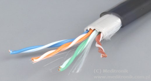
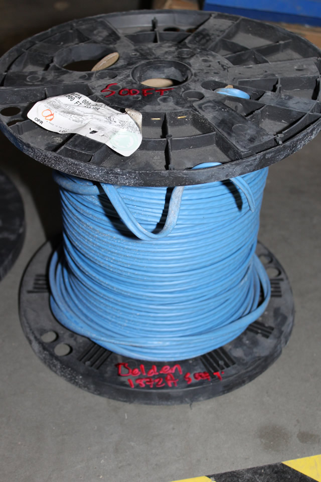
    - สายแลนทั้งหมดใช้ Belden 1872A Multi-Conductor - Enhanced Category 6 Bonded-Pair Cable


    ที่มองไว้
    - Cisco SRW2048-EU 48-Port Gigabit Switch > datasheet

    - 3Com Baseline Plus Switch 2952 48-Port Gigabit Switch > datasheet

    - Belden 1872A Multi-Conductor Enhanced Category 6 Bonded-Pair Cable > datasheet
    ( มีของเก่าเหลืออยู่ )
    Description : 23 AWG Bonded-Pairs, Solid Bare Copper Conductor, Non-Plenum, Polyolefin Insulation, Rip Cord, PVC Jacket
    Suitable Applications : Premise Horizontal Cable, Gigabit Ethernet, 100BaseTX, 100BaseVG ANYLAN, 155ATM, 622ATM, NTSC/PAL Component or Composite Video, AES/EBU, Digital Video, RS-422, Noisy Environments
    Operating Temperature Range : -20C to +80C
    Telecommunications Standards : Category 6 - TIA 568.C.2
    --- สายแลนBeldenรุ่นนี้ถือว่าคุ้มมาก ใช้งานที่ร้านนี้มา5ปีกว่า ไม่เคยเจอปัญหาไรเลย ---
    --- ของเดิมเพื่อนใช้ของAmp 9-1427200-6 Cat6 สีฟ้า พอมาที่ร้านเห็นBeldenตัวนี้ เค้าเลิกใช้Ampไปเลย ---

    Last edited by keang; 21 Jan 2012, 18:58:20.

    Comment


    • ของ cisco นี่ที่บริษัทใช้ในส่วนnetwork หลัก ติดยี่ห้อ cisco แต่จะมีบวกservices ต่างๆเพิ่มมาให้
      ก็คือซื้อของพ่วง services แต่ถ้าใช้ธรรมดา Linksys ก็ดีครับ(ก็คือ cisco แหละ) ถูกกว่า(แต่ก็ยังแพง)
      ในรุ่นที่เทียบกันได้ข้างในแทบจะเหมือนกันเลย

      3com นี่เคยใช้สมัยก่อนหลายปีมาละ ประสิทธิภาพใช้ได้ทำงานไม่มีปัญหา แต่ที่มีปัญหาตอนนั้นคือ
      power supply มีปัญหาแทบทุกตัวเลย ไม่ใหม้ ก็ติดๆดับๆบ้าง เวลาใช้ไปนานๆหน่อยแล้ว
      ก็เลยไม่ได้ใช้อีก ไม่รู้เดี๋ยวนี้ดีขึ้นยัง แต่รู้สึกหลังๆมานี่ 3com ค่อนข้างตกๆไปน่ะ
      ไม่ค่อยเห็นคนทำใบเสนอราคายี่ห้อนี้มา เห็นแต่ Linksys, Netgear, SMC

      Netgear นี่ก็มาแรงนะ ลองหาข้อมูลดูครับ

      Originally posted by keang View Post
      ใช้งานในร้านเกมครับ
      - ซัพพอร์ท Jumbo Frame
      - Teaming VLAN 3เส้น (Intel PRO/1000 PT Server Adapter)
      - Lan Disk ซัพพอร์ท30เครื่อง (ใช้โปรแกรม iSCSI Cake)
      ...
      ตามนี้ SMC ก็น่าจะเหมาะดีเหมือนกัน
      ผมใช้ SMC ที่ห้องออฟฟิศ และก็ใช้ที่บ้านด้วย ก็ดีนะไม่มีปัญหาอะไร แต่เป็นรุ่นเล็กหน่อยน่ะครับ
      ถ้าดูจากคุณภาพของรุ่นเล็กแล้วคิดว่ารุ่นใหญ่ก็น่าจะใช้ได้ดีเหมือนกันนะ

      SMC นี่ก็เป็นเจ้าแรกๆที่เล่นกับ Jumbo frame นะ ลองดูข้อมูลรุ่นนี้ครับ
      <<SMC8150L2 TigerSwitch 10/100/1000>>

      จับคู่กับ Network card รุ่นนี้
      <<SMC9452TX-2 EZ Card 10/100/1000>>
      Support Jumbo frame ทั้งคู่ น่าลดปัญหาปวดหัวเรื่อง driver (หลายเครื่องน่าจะ ghost กันมาได้เลย)
      และความ compatibleกัน เพราะ Jumbo frame นี่ค่อนข้างจุกจิกน่ะผมว่า
      network, อุปกรณ์ต่างๆ ต้องเป็น Gigabit ทุกตัวและต้อง support Jumbo Frame ทุกตัวด้วย
      และต้องเซ็ต MTU ให้เท่ากันทุกตัวอีก ไม่งั้นมีปัญหา Fragments, frame loss, etc. แล้วNetwork จะช้าลงไปเลย
      แต่ถ้าเซ็ตลงตัวแล้ว Transfer Data ใน local นี่เร็วเลยละ

      Comment


      • ขอบคุณครับ
        มีของแถมเรื่องทริคสำหรับJumbo Frameให้ด้วย

        3Comที่ผมเคยใช้เป็นรุ่นBaseline Switch 2824ใช้คู่กับสายแลนของBelden ใช้กับร้านที่สำเหร่ 5ปีกว่ายังไม่เจอปัญหาไร

        อาจจะโชคดี ตัวที่ได้มาไม่ใช่ของทำในจีนเลยไม่เจอปัญหาไรเลย
        เพราะอีกหน้าร้านนึงที่บางบัวทอง ซื้อทีหลังเกือบ2ปี ได้ของที่ทำในจีน ตอนนี้เจอพอร์ทเสียไปพอร์ทนึงละ

        Comment


        • PS Audio Ultralink


          PS Audio Ultralink Two


          PS Audio Ultralink Two - MOD เท่าที่ดูคร่าวๆ เปลี่ยนหม้อแปลง กับ เพิ่มออปชั่น"HDCD Module"


          Comment


          • credit > wiringschematics.net , powersupply88.com


            ON-OFF Touch Switch Circuit เผื่อใครจะเอาไปใช้ ปิด-เปิด เครื่องdacหรือแอมป์หูฟัง


            IC1 : 555 timer IC
            Q1 : BC547
            D1 : 1N4148
            D2 : Red LED 3 or 5 mm.
            R1, R2 : 3.3M
            R3 : 10K
            R4 : 1K
            C1 : 10nF 63V
            JF1, JF2 : Metal Plate
            RL1 : 12V Relay

            This is the On-Off touch switch circuit project. Modern mechanical switches are improved compared with those old technology. But sometimes we need to replace an old switch, or to control the electric current which is higher than the strength of switch to deliver a supply, or you need a switch that has more contemporary appearance. For these and other purposes, it is the essential the above circuit.

            This circuit is simple and easy in construction and componentss which are required to build this circuit can be found at every electronic parts store. It is based on the famous 555, which drives a relay whose contacts play the role of the switch. These metal surfaces can have a form that we want, but must be clean and close the circuit. You just need to touch one of the two metal surfaces to change the condition of the switch/contacts of RL1. The surface JF1 is used to close the contacts of RL1 [ON] or surface JF2 is used to open the contacts of RL1 [OFF]. The current will be controlled by RL1 is dependent on contacts. The Led D2 will be turned on when switch is in ON position and the contacts of RL1 closed.


            ---------------------------------------------------------


            Soft-Start and Pulse Transformer Power Supply


            When you switch power supply amplifiers, laboratory and other PS in the network there is interference caused by triggering currents of transformers, charge currents of electrolytic capacitors and the start of powered devices themselves. Outwardly, this interference manifests itself as a "blinking" light pops and sparks to an electrical outlet and electrically ? this drawdown line voltage, which can lead to failure and instability of other devices that are powered from the same network.

            In addition, these inrush currents cause burning of contacts of switches, power outlets. Another negative impact of inrush current ? rectifier diodes at the start of this work by the current overload and could be damaged. For example, the inrush current charging the capacitor 10,000uF 50V can reach more than 10 amps. If the diode bridge is not designed for this current operating environment may bring the bridge down. Especially strong inrush currents seen at a power 50-100W. For these power units offer the starter.

            When you enable the network adapter current limiting resistor starts through R4. After some time needed for its start, capacitor charging and starting load resistor shunted by relay contacts and the power supply output to full capacity. Closing time is determined by the capacitance of the capacitor C2. C1, D1, C2, D2 elements are transformerless power supply for control circuit relay. Zener diode D2 plays a purely defensive role, and an intact control scheme may be missing. Relay BS-115C-12V, was used in the scheme may be replaced by any other relay contacts with a current of at least 10A, with the selection of diodes, a capacitor C1 and the choice of transistor VT1 on voltages, high voltage relay. Zener diode D3 provides hysteresis between the voltage on and off switch. In other words, the relay will turn sharply, but not smoothly.

            The capacitor C1 determines the current of the relay. In case of insufficient current capacity of the condenser must be increased (0.47-1uF 400-630V). In protective wrap for the capacitor is desirable to put on tape or shrink it up. Fuses are selected on the two-times the rated current of power supply. For example, for a 100W power supply fuses must be current on 2 * (100/220) = 1A. If necessary, the scheme can be complemented by a network balanced / unbalanced filter on after the fuses. Connection with the case, which is present in the scheme can be regarded only as a common wire to connect the tester. In no case can it connect to the chassis device, display it on the general wire-line filters, etc.


            ---------------------------------------------------------


            Low Voltage regulators with short circuit protection


            These Low Voltage regulators with short circuit protection can provide 6, 7.5, and 9 V from an automobile battery supply of 13.5 V nominal, however, they will function just as well if connected to a smoothed dc output from a transformer/rectifier circuit.

            Two types are shown for both positive and negative ground systems. The power transistors can be mounted on the heatsink without a mica insulating spacer thus allowing for greater cooling efficiency. Both circuits are protected against overload or short-circuits. The current can?t exceed 330 mA. Under normal operating conditions the voltage across R2 does not rise above the 500 mV necessary to turn Q2 on and the circuit behaves as if there was only Q1 present. If excessive current is drawn, Q2 turns on and cuts off Q1, protecting the reg-ulating transistor. The table gives the values of R1 for different zener voltages.


            ---------------------------------------------------------


            Dual Polarity Power Supply +/- 15V based Transistors


            This Dual supply circuit is suitable for installation of power analog (audio or measurement), it provides a bipolar voltage with voltage source between 20 and 50 V (in audio power amp, for example). Regulated output voltage is 15V, but can be adjusted from + /-12V or + /-18V by simply changing two components. The maximum output current must not exceed 100 mA each branch.

            If you ask, where the transformer and diode rectifier?
            This circuit is intended to be transplanted into an existing circuit (eg audio amp), which already provides symmetric voltage between + /-20V and + /-50V.

            Reduction and voltage regulation
            The settings output voltage is provided by two zener diodes D1 to D2 for positive and negative branches. The polarization of the two diodes are provided respectively by R1 and R2. ?Power? of the series was entrusted to two transistors BD139 and BD140, which should also be provided with a heatsink to ensure proper cooling. It may seem strange when should put some of the heatsink for low power output (max 100 mA). But the reality is that both transistors will be able to dissipate high power in this case max current .

            The output voltages are not equal to 15V!
            If you measure + / -14.5 V output instead of + /-15V, do not worry, it?s normal. Voltages + /-15V are determined by the zener diodes, which are likely to have a voltage different from one model to another (the dispersion characteristics are quite large). Moreover, the two transistors are connected in voltage follower, meaning found on the emitter, the voltage applied to the base, unless the fall of base-emitter voltage is in the range of 0, 6V. In practice, you should find out, a voltage can be between 14 V and 15.5 V. Outside this range, you can consider that there is a problem and you should check the wiring and the condition of the components.

            Modification of the output voltage
            Just replace the zeners D1 and D2. The value of 12V is limited, if you go under, the voltage drop across the transistors will continue to rise and they will heat up more. The value of 18V or 24V, however, is more acceptable, but be careful if the supply circuit contains op amp, the maximum voltage generally accepted for these is + /-18V! You may need to decrease slightly the value of resistors R1 and R2 if the zeners are 24V and the input voltage is ?only? 30V.
            Last edited by keang; 22 Jan 2012, 16:33:35.

            Comment


            • @...@
              Last edited by jinn; 30 Jan 2012, 19:17:06.

              Comment


              • ^^ ถูกครับ แต่ไหนๆจะทำไปกัดใหม่ ก็ใส่อักษรกำกับ บน, ล่าง ไว้สักหน่อยกันสับสน(ทั้งคนกัด และคนใช้)
                และเติมจุดบอกขา 1 ไว้อีกนิด กันหลงลืม ก็ดีครับ พอดีผมไม่ได้ใส่ไว้ตั้งแต่ตอนแรก

                แต่... สงสัยว่าจะเอาไปส่งกัดเรียบร้อยแล้ว ไม่ได้แวะมาซะหลายวัน

                -----------------------------

                หยุดไปเที่ยวตรุษจีนซะหลายวัน อิอิ งานยังไม่เดิน ได้เวลากลับมาเริ่มทำ Prototype ต่อละ
                ทิ้งไว้หลายวัน

                Comment


                • Originally posted by keang View Post
                  credit > wiringschematics.net , powersupply88.com


                  ON-OFF Touch Switch Circuit เผื่อใครจะเอาไปใช้ ปิด-เปิด เครื่องdacหรือแอมป์หูฟัง
                  ...
                  ขอบคุณมากครับ

                  Comment


                  • จัดให้...( ไม่รู้ทำมาถูก... อะ่ป่าว เนี่ยนะ )

                    จับกลับหน้า...กลับหลัง กลับหลัง เอากันเอง..นะเด้อ...

                    แก้แบบ อยู่ ครับ..
                    Last edited by jinn; 30 Jan 2012, 20:14:23.

                    Comment


                    • หาเรื่องปวดหัวดีกว่า

                      Pulse Transformer สำหรับทำอินพุทS/PDIF ระหว่างใช้แกนเดี่ยวกับฝอย
                      คิดว่า แต่ละแบบ น่าจะมีผลอะไรด้านไหนบ้างครับ

                      Comment


                      • Pulse Transformer ต้องหาของดีๆมีเกรดหน่อยครับหรือไม่ก็หา แกนโดนัทมาพันเล่นดูเองก็ได้ครับ
                        เพราะถ้า ของไม่ดีเคยเจอเสียงจะมัวๆขาดน้ำหนักเสียงยังไงก็ไม่รู้ครับ เอา C เกรดดีๆ 0.1uf มาต่อ
                        ยังเสียงดีกว่าอีกครับ

                        ช่วงนี้ผมก็เขียน PHP ยาวเลยครับ สงสัยคงไม่ได้ DIY ไปทั้งเดือนแน่ ToT

                        Comment


                        • @jinn

                          อ่า... กลับหัวกลับหางนิดหน่อยน่ะครับ
                          ผมออกแบบไว้ให้ op-amp single 2ตัว วางกลับหัวกลับหางกัน เพื่อให้ระยะสัญญาณมันสั้นและเท่าๆกันน่ะครับ
                          แก้ให้ดูรูปนึง จะประมาณนี้ครับ

                          Comment


                          • Pulse transformer ถ้าจะพันเองก็พอทำได้นะครับ
                            ใช้แกน toroid แบบ high mu (>4000)
                            Primary กับ secondary ใช้ลวดอาบน้ำยาขนาด 0.5 mm พันอย่างละ 6 รอบ (1:1)
                            ก็พอใช้เล่นได้ดี(บ้าง)น่ะครับ

                            สำหรับถ้าเป็นการต่อเชื่อมสัญญาณกับตัว pulse trafo ก็ควรใช้แบบแกนเดี่ยวน่ะครับ เพราะ impedance มัน กระเพื่อมน้อยกว่า
                            และuniform กว่าแบบแกนฝอย แต่จริงๆแล้วสำหรับระยะไม่มาก ก็แทบไม่เห็นความแตกต่างน่ะครับ เพราะงั้นใช้แบบไหนก็ตามสะดวกครับ
                            ---------------------------

                            เสาร์ อาทิตย์ว่าจะทำ ODG-DAC prototype ต่อซะหน่อย ก็ต่อไปบ้างเกือบๆละ
                            แต่ต้องไปปล้ำกับ PSU แทน เพราะดันไปเล่นซน เอาไปต่อลองนู่นลองนี่ ทำมันช็อตซะ ต้องมานั่งไล่ นั่งซ่อม
                            ใช้ SMD หลายตัวซะด้วย 555+

                            สำหรับตัว บอร์ดDAC ลองๆต่อแล้ว+เช็ควงจร คงต้องปรับนิดหน่อย ไม่หน่อยละหลายอย่างเหมือนกัน
                            ไว้เดี๋ยวลองทำให้workดีๆหน่อยก่อน แล้วจะได้รวบรวมรายละเอียด/รายการที่ต้องปรับ แล้วจะได้ส่งให้คุณkeang กับคุณWizardmans
                            พร้อมกับPCB เลยครับ

                            Comment


                            • Originally posted by MONOLAB
                              Pulse Transformer ต้องหาของดีๆมีเกรดหน่อยครับหรือไม่ก็หา แกนโดนัทมาพันเล่นดูเองก็ได้ครับ
                              เพราะถ้า ของไม่ดีเคยเจอเสียงจะมัวๆขาดน้ำหนักเสียงยังไงก็ไม่รู้ครับ เอา C เกรดดีๆ 0.1uf มาต่อ
                              ยังเสียงดีกว่าอีกครับ
                              Originally posted by dracoV
                              Pulse transformer ถ้าจะพันเองก็พอทำได้นะครับ
                              ใช้แกน toroid แบบ high mu (>4000)
                              Primary กับ secondary ใช้ลวดอาบน้ำยาขนาด 0.5 mm พันอย่างละ 6 รอบ (1:1)
                              ก็พอใช้เล่นได้ดี(บ้าง)น่ะครับ

                              สำหรับถ้าเป็นการต่อเชื่อมสัญญาณกับตัว pulse trafo ก็ควรใช้แบบแกนเดี่ยวน่ะครับ เพราะ impedance มัน กระเพื่อมน้อยกว่า
                              และuniform กว่าแบบแกนฝอย แต่จริงๆแล้วสำหรับระยะไม่มาก ก็แทบไม่เห็นความแตกต่างน่ะครับ เพราะงั้นใช้แบบไหนก็ตามสะดวกครับ
                              ขอบคุณสำหรับข้อมูลและแนวทางเรื่องPulse Transformerครับ
                              มีโอกาสมีเวลาคงได้ลองเล่นสนุกแบบแปลกๆครับ

                              ลวดอาบน้ำยาขนาด 0.5 mm นี่มันประมาณลวดเบอร์ไรครับ


                              --------------------------------------------------------


                              รูขาไอซีของPCB ใส่ซอคเกทไอซีตัวนี้ได้หรือเปล่าครับ
                              Last edited by keang; 30 Jan 2012, 18:58:29.

                              Comment


                              • แก้แบบ...ครับ @....@
                                Last edited by jinn; 31 Jan 2012, 12:37:01.

                                Comment

                                Working...
                                X