Announcement

Collapse
No announcement yet.

[D.I.Y. + Project Log] ลองทำ DAC + Amplifier เล่นเองดีกว่า(?) ผมเรียกมันว่า FuWa :)

Collapse
X
 
  • Filter
  • Time
  • Show
Clear All
new posts

  • AkudSdac prototype ร้องเพลง

    AkudSdac First Singing! - Up to PCM24/192 and DSD64 support.


    AkudSdac ร้องเพลงละ อิอิ พอร้องเพลงได้ เห่อ เอามาอวดก่อน


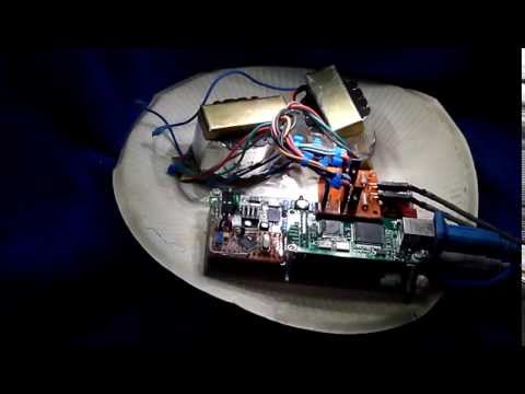
    AkudSdac First Singing! - TEST.
    USB DAC (AK4396 + Combo384)
    + Up to PCM 24bit/192KHz and "DSD64" supports.
    + One connection; using only 1 USB cable for both Data and Power: maximized portability, mobility :-)

    Note:
    This is the first run to test functionality and if it's workable.
    It;s work! Btw.
    So... There're areas that need to be checked and improved.
    The controller firmware still in preliminary stage, just make it wok.
    Thus, just ignore those popcorn and cracker (between mode changed and track changed). haha
    I'm in the process to Iron Out The Kinks.
    And, with that make?shift output circuit (filters and output trafo.s.)
    may need to be re-designed. (but it sounds OK, still, right?)

    'nuf rants. 8)

    กลับบ้านมาค่ำๆ ยังฯส่าห์ขยันมาเขียน firmware ใส่ซะหน่อย
    จะได้ร้องเพลงซักที
    Controller firmware ก็ให้ทำงานได้ก่อนอ่ะนะ ยังต้อง ปรับปรุง fine tune รีดเรียบๆ 555+
    ไว้มีเวลาลองเพิ่มเติมก่อน
    เพราะงั้นก็เสียงปุ้กปั้กเป๊าะแป๊ะ เวลาเปลี่ยนโหมด/แทรก ก็ทำหูทวนลม ว่าไม่ได้ยินก็แล้วกันนะ
    ไว้มีเวลา(อีกแล่ว จะมีไหม) ออกแบบวงจรส่วน filter+output อีกซักหน่อย ซักแบบสองแบบ เล็กๆหน่อย
    ตอนนี้ก็เอาแบบนี้เล่นก่อน Output Trafo.

    ไว้มาเล่าต่อละกัน

    Comment


    • สอบถามครับ Capacitor ที่ขวางทางสัญญาณ Coaxial ก่อนส่งไป DIR9001
      ค่าที่เหมาะสม ควรใช้ค่าเท่าไหร่ครับ เข้าใจว่ามันเกี่ยวกับ Noise
      แต่เห็นใช้กันตั้งแต่ 0.01uF - 1uF กันเลยทีเดียว

      Comment


      • R-C Filter มั๊งครับ
        Resistor (75ohms)Capacitor (0.01uF)Corner Frequency (212314.2Hz)
        Resistor (75ohms)Capacitor (0.1uF)Corner Frequency (21231.4Hz)
        Resistor (75ohms)Capacitor (1uF)Corner Frequency (2123.1Hz)
        wav 16bit/44.1khz
        pcm=44100*16*2=1411200hz(1.41mhz)
        เดานะ

        Comment


        • อีกนิดครับ ถ้าคิดแบบความถี่สูงผ่านโดยใช้ 1/(2PI)(F)(C)
          โดยที่ C 0.1uF จะไม่ยอมความถี่ที่ต่ำกว่า 21231.4Hz ผ่านไปได้
          ถ้างั้น หมายความว่า Noise ของสัญญาณ Digital จะอยู่ในช่วงของความถี่ต่ำ ถูกไหมครับ
          จึงควรใช้ C ค่าน้อยๆ เพื่อไม่ยอมให้ Noise ผ่านไปได้ เพราะยังไงไม่มีผลกับสัญญาณ Digital อยู่แล้ว
          เพราะ Data ของมันอยู่ในช่วงของความถี่สูง หรือเปล่า?????
          Last edited by Angelprime; 27 Apr 2014, 07:48:00.

          Comment


          • ในส่วนทางเดินสัญญาณดิจิตอล หน้าที่หลักคือกันไฟตรงครับ เรื่องกรองความถี่นี้คงเป็นเรื่องรองลงมา เพราะความถี่ที่ใช้มันสูงเกินกว่าที่มันกรองมาก
            บางเจ้าจะใช้แบบหม้อแปลงแทน (pulse transformer 1:1)

            ประเด็นที่ผมสนใจมากกว่าคือ สัญญาณมันเข้าแล้วออกมาหน้าตายังเหมือนเดิมรึเปล่า??? transient respond ของcมันดีรึเปล่า สัญญาณขาออกมีovershotรึเปล่า
            ถ้ากลับไปดูหน้าเก่า(ขออภัยน่ะครับขี้เกียจไปรื้อแล้วquoteมาให้ดู) จะเห็นคุณkeang โพสต์ cd transport ที่เขาวัดสัญญาณดิจิตอลขาออกมัน เบี้ยวกันสุดๆไปเลย มันไม่เป็นsquarewaveแล้ว

            Comment


            • อ่าน3เม้นท์บนจบ มีความรู้สึกเกิดขึ้นในใจทันที : อุทานในใจ "โห....." เห็นแล้วอึ้งเลย
              ไม่ไช่การเดามั่ว แต่ใช้พื้นฐานความน่าจะเป็น เป็นตัวอ้างอิงด้วย

              ถ้ามีใครมาถามผม ผมคงไม่คิดไรเลย คงบอกว่า ไม่รู้เหมือนกัน เค้าใช้กันประมาณนี้ ก็ตามๆเค้าไป
              Last edited by keang; 27 Apr 2014, 14:51:26.

              Comment


              • อ่านทั้ง 4 โพสต์
                หาข้อมูลกันมาแชร์กัน ดีครับ
                ใช่ครับ เป็น filter(High pass) และ DC blocker ค่าที่ใช้ได้ ก็ ตามที่คุณAngelprime หาข้อมูลมาน่ะครับ
                เพราะทั้งหมดจะผ่านสัญญาณ SPDIF ที่มีความถี่สูงได้
                เพราะงั้นก็มาถึงว่าใช้ค่าเท่าไหร่ดี ก็มันใช้ได้หมดนี่ ก็เอาตัวที่เขานิยมใช้เป็นกึ่งๆมาตรฐาน คือ 1uF ครับ
                ผมก็ใช้ตามๆเขาเหมือนกัน
                เพิ่มเติมนิด C ค่าน้อยจุดตัดความถี่มันก็สูงขึ้น ก็อาจส่งผลไปเบียดตัวสัญญาณหลักได้ครับ

                อีกนิด สำหรับที่คุณแมวว่าว่า รูปคลื่นสัญญาณจากรูปที่คุณkeangเคยเอามาให้ดูมันเบี้ยวๆไม่เป็นรูป square wave แล้ว
                แต่ มันก็ทำงานได้ถูกต้อง ก็เพราะสัญญาณมันความถี่สูงน่ะ ระดับ MHz up

                จากรูปเขา zoom in เข้ามาให้เห็นรูปสัญญาณ เพราะงั้นถ้าzoom out ออกมาปกติ ทั้ง2รูป รูปสัญญาณเบี้ยวกับรูปสัญญาณสวยๆ
                ก็หน้าตาเหมือนกัน เวลาเอาไปใช้สำหรับสัญญาณdigital จะเอาไปใช้โดยการ sync กับ Clock อีกที
                ไม่เหมือนสัญญาณ Analog ที่ใช้ทั้งลูกคลื่น

                เพราะงั้นก็สนใจเฉพาะจุดที่ สัญญาณกับClock มัน sync กัน ว่าได้ค่าเท่าไหร่ เอาไปเที่ยบเป็น HIGH หรือ LOW (1 or 0)
                ก็ใช้งานได้ค่าถูกต้องเหมือนๆกัน ตามทฤษฎี แต่ในทางปฏิบัติ ตัวสัญญาณไม่สวยก็ย่อมมีโอกาศผิดพลาดได้มากกว่าน่ะครับ
                ผิดพลาดมากหรือน้อยก็แล้วแต่ ถ้ามากเกินข้อกำหนดก็คือใช้งานไม่ได้นั่นเอง

                ------------------------------------
                PS. ใครรู้ใครเห็น ว่าเจ้า Wheel volume pot แบบนี้มีขายที่ไหนบ้างครับ รบกวนบอกพิกัดหน่อย

                ขอบคุณครับ
                Last edited by dracoV; 27 Apr 2014, 18:00:57.

                Comment


                • วอลลุ่ม : ถ้าเป็นเมื่อก่อน มีขายหลายร้านเลย แต่เดี๋ยวนี้แทบไม่มีใช้กันแล้ว ต้องเดินถามร้านขายแล้วละมั้ง เพราะ ต้องเทียบขนาดด้วย
                  หูฟังร้านเกม แบบที่มีกระเปาะปรับเสียงที่ตัวสายจะใช้ตัวนี้ทั้งนั้น ถ้าหาไม่ได้และจำเป็นต้องใช้ สงสัยต้องไปแงะจากหูฟังร้านเกมมาใช้แทน

                  ------------------------------

                  มีใครเคยลองบริดจ์ไดโอดของฝั่งรัสเซียบ้างมั๊ย ตัวเป็นแบคกาไลท์ ไม่รู้เสียงเป็นงัยบ้าง
                  Last edited by keang; 27 Apr 2014, 21:50:48.

                  Comment


                  • สงสัยต้องสั่งจากพี่จีนอีกแล่ว พี่แกมีทุกอย่าง ดีม้่งไม่ดีมั่ง (จริงมั่งปลอมมั่ง) แต่ก็มี

                    Comment


                    • I/V for the DAC s current vihodom
                      The only drawback of the proposed converter I/V discrete bipolar transistors is:
                      - A relatively large area that it occupies on the board.
                      - For maximum performance you need to ensure close to the ideal and complementary transistors VT7 VT9.

                      It was therefore decided to develop a new inverter I/V which does not have these disadvantages and provide even better quality. The scheme proposed converter I/V with 2nd order lowpass filter with a stable group delay shown in the attachment (with options for DAC curves. 2mya current + (PCM63, PCM1700, TDA1541, TDA1540), +-1mA (AD1856, AD1851, AD1860, AD1861 , AD1862, PCM56, PCM51, PCM61, PCM58, PCM64, PCM1702, PCM1704) and PCM67/69.

                      Capacitors C1, C2, C3 should be of the highest quality (NP0, foil polypropylene, polystyrene). Resistors R1, R3, R4 carbon (Riken Ohm, Ohmite Little Demon, Ohmite Little Rebel, Allen Bradley, etc) or tantalum or qualitative metal film, the output T may be used filter requirements for an application of the same parts as described above.


                      For 2x 1541 or parallel conveyor 750 R1 = R2 = 2.2k C1 = 1500p C2 = 3900p
                      4x for 1541 R1 = 390 R2 = 1.2k C1 = 3300p C2 = 7500p


                      30kHz for C2 = C3 = 560pf 560pf


                      Good luck and good sound!

                      Literature:
                      1) M. Hawksford "Current-steering transimpedance amplifiers for high-resolution digital-to-analogue converters", 109th AES Convention, Los Angeles, September 2000
                      2) E.Barnes "Current feedback amplifiers" Analog dialogue 30-3, 30-4
                      3) I.Dostal "Operational Amplifiers" Moscow "Mir" 1982r.
                      4) P. Horowitz, U.Hill "Art circuitry" Moscow "Mir" 1998r.
                      5) Marcinkevi?ius, Bagdanskis "Speed ??ICs DAC and ADC and measuring their parameters" Moscow 1988r.
                      6) Documentation of the AD844, AD846, AD811

                      -------------------------------


                      I/V for the DAC s current vihodom 2
                      Inverter current \ voltage with a frequency-dependent Wasps referred to as "844 5534" was developed neskolkolet ago and has shown good results, but was quickly made ??a small change in the scheme provide a better suppression band LPF detention and to ensure the best outcome subjectively. True, I had not bothered to paint and put this change, but the same answer all the time by e-mail, etc. is already a little tired of the same seen so little time to draw this option, which you can see below for a converter for PCM63 and PCM1702 / PCM1704.


                      Resistors in a T-filter at the output node and a resistor R1 to be the finest quality, it is desirable metal film also resistors in a T-filter can be replaced by suitable powerful (for the current 5-10A) ferrite beads.

                      For those who want to get a different sound can experiment with the output buffer, some versions of which are shown below, for example good monolithic buffers type BUF03, LM6121. Or discrete bipolar or FET. Each of the options will only give him a little inherent color. In the case of DU as a buffer to ensure the accuracy of sound is better to use vysokolineynye OS (in the case of ensuring the correct wiring \ lock for their normal operation) type LME49990, LME49710, LT1468, SE5534 (their chains correction) and LM6171. For lovers of the great and persistent stains, you can use certain types of OS specifically for this purpose, for example OP42, OPA604 etc..

                      In general, experiment to your taste.


                      -------------------------------


                      I/V for AD1955
                      Food OPA860 + -5,5 in op amp differential. need to use the amplifier LME49710, LME49870, LM318, LT1468, LM6171 or any other food to taste + 12c. Resistors desirable MELF, capacitors exclusively NP0.


                      -------------------------------


                      Single-Ended Current-feedback (in audio band) converter I/V
                      Most parallel DAC has current output. Therefore, there is a problem - how to convert current to voltage, ideally without distortion? Today mainly use two methods: the classic - at the Shelter, the resistor.

                      At first glance, the resistor converter option is ideal (Ohm's law), but in reality it has drawbacks. DAC to provide their passport details should work on zero input impedance converter I / U. When non-zero input impedance I / U Keys DAC external voltage is applied steady voltage drop across the resistor I / U which in turn worsens the HP DAC. With low resistance resistor resultant voltage will be very small (20-50mV) and there is another problem - how to enhance the signal quality to the desired level?


                      Option converter I / U on the OS (Fig. 1) is a classic, it can be found in any book on the circuit design, but it is ideal only if the ideal (ie not being implemented in practice) OS. To work as an I / U op amp must operate in a mode without limiting the rate of voltage change (intermodulyatsiynih not to introduce distortion), and also have a zero input impedance over a wide bandwidth. These conditions are not fully satisfied for any ETA running voltage or Current Feedback for ETA. Input impedance at RF in both species is inductive by reducing the RF gain, as well as (for Current Feedback OP) because the stage with common base HF has inductive input impedance before coverage DUS. The best types of Current Feedback Op Amps provide the rate of change of the output voltage 1000 - 5000V/mks, really need to choose Current Feedback Op Amps with a maximum input current to a push-pull structure despite the front end as long as possible in the class A, otherwise they will reach a steep front in AB mode ( will only work one half UN) with all the consequences ...


                      But apart from these two, there are other ways, such as transformer (which resale zashuntovana resistor), the transistor included in the common base (Fig. 2). Option converter I / U with transistor ON is very simple, just 4 resistors and one transistor, but it has disadvantages such as non-zero input impedance drift "zero", a relatively large output resistance and lack of linearity. But these flaws can be corrected.


                      The scheme proposed single-cycle current-voltage converter (Fig. 3) consists of an input stage and the output of the voltage follower. The input stage - with a common base transistor VT2. Transistor VT1 VT2 sets the offset for the zero potential for the emitter VT2 (DAC output). VT2 collector current reflects current mirror VT5, VT6, VT7 sings the collector current changes and VT1 VT2 are identical (PIC), which in turn provides a theoretically zero input impedance of this stage. Constant current generator created on the basis of the current mirror VT8, VT9 sets the initial bias current for VT2. To provide a "zero" on the emitter VT2 (DAC output) Used cascode switch VT1, VT2, which allows to equalize power allocated to them and accordingly the temperature of their crystals. Output voltage follower based on a modified cascade common-collector load as an active power source, it can significantly reduce the distortion of this stage, as well as increase the ability nagruzuchnuyu (minimum load resistance 1k).

                      Both cascade at low frequencies covered by the current feedback (Current-feedback) through R1, thus reducing the output impedance, and reduce distortion inverter I / U in general. At high frequencies, the feedback input stage covered only through the filter capacitor C2.

                      Capacitor C1 200-2000 pF capacitance reduces the input impedance of the transducer at high frequencies (10 MHz and above). Capacitor C3 prevents self-oscillation of the input stage. Inductance L1 is a ferrite bead, it prevents interference from RF output in terms of the feedback transducer. Instead, you can put a resistor L1 50-200 ohms, but its impact on the sound quality will be significant. If you change the resistor R1 feedback must be recalculated capacitance C2. Resistors R2, R3, R4, R6, R7, R8, R9 are designed to reduce the effect of Earley (dependence of the collector current of the emitter-collector voltage). Elements VT14, R12, R13, R14 are set in the case of using the DAC TDA1540, TDA1541, TDA1541A (/ R1, / S1, / S2). "Zero" at the inverter output (emitter VT13) exhibited by changing the resistor R7 (or R6) within a small range (10 - 40 ohms). In the case of TDA1540, TDA1541, TDA1541A (/ R1, / S1, / S2) "zero" exhibited by changing the resistor R14. For best results, you must choose the current mirror transistors VT5, VT6, VT7 also VT8, VT9 and VT10, VT11. BC547 transistors can be replaced by BC550, 2SC2240. BC557 transistors can be replaced by BC560, 2SA970. BF246 transistor can be replaced by any FET with an n-channel (or counting the value of resistors R13, R14). Capacitors C1, C2, C3 should be of the highest quality (the foil polypropylene, polystyrene). Resistors R1, R8, R9, R10 coal (Riken Ohm, Ohmite Little Demon, Ohmite Little Rebel, Allen Bradley, etc.) Or tantalum or qualitative metallofolgovye.

                      Good luck and good sound!

                      Literature:
                      1) M. Hawksford "Current-steering transimpedance amplifiers for high-resolution digital-to-analogue converters", 109th AES Convention, Los Angeles, September 2000
                      2) E.Barnes "Current feedback amplifiers" Analog dialogue 30-3, 30-4
                      3) I.Dostal "Operational Amplifiers" Moscow "Mir" 1982r.
                      4) P. Horowitz, U.Hill "Art circuitry" Moscow "Mir" 1998r.
                      5) Marcinkevi?ius, Bagdanskis "Speed ??ICs DAC and ADC and measuring their parameters" Moscow 1988r.
                      Last edited by keang; 7 May 2014, 10:21:43.

                      Comment


                      • How to make a Current to Voltage Converter with an Op Amp

                        Comment


                        • Regular Versus Precise Full Wave Rectifier Part 1

                          Comment


                          • Simple Half Wave Rectifier Example with Op Amp Part 2

                            Comment


                            • A Simple Trick to Improve Half Wave Rectifier Performance with Op Amp Part 3

                              Comment


                              • Precise Full Wave Rectifier Example with Op Amps Part 4

                                Comment

                                Working...
                                X