 Tweet
Tweet
โอ๊ย อยากทำ แย้ว แต่ไม่มีเวลาซื้อของเยย พี่คนไหนว่างๆ บ้าง คราบ ฝากซื้อของนิดนึง
-
-
อยากโมแต่ทำไม่เป็นเลย ทำไงดีComment
-
จะโมอะไรเหรอครับ เอารูปมาโพสแล้วช่วยกันคิดก็ได้Comment
-
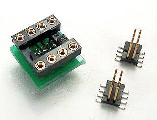
อะหลั่ยบางส่วนของชุดแรกที่เดินทางมาถึงแล้ว
อะหลั่ยบางส่วนของชุดแรกที่เดินทางมาถึงแล้ว
IC Socket Gold Plated
Military Grade


ใส่โมเครื่องเล่นPlayer เครื่องHome
ใส่โมการ์ด X-Fi Titanium HD ของ TuiLor อะหลั่ยด้านใต้PCBทุกตัวต่อที่ขาซ็อคเกทโดยตรง (ลดการสูญเสียจากการใช้PCB)
ใส่โมการ์ด ASUS Xonar Essence ST / STX อะหลั่ยด้านใต้PCBทุกตัวต่อที่ขาซ็อคเกทโดยตรง (ลดการสูญเสียจากการใช้PCB)
ใส่โมการ์ด ASUS Xonar HDAV1.3 Deluxe อะหลั่ยด้านใต้PCBทุกตัวต่อที่ขาซ็อคเกทโดยตรง (ลดการสูญเสียจากการใช้PCB)
ใส่คู่หน้าของ Auzen X-Fi Prelude อะหลั่ยด้านใต้PCBทุกตัวต่อที่ขาซ็อคเกทโดยตรง (ลดการสูญเสียจากการใช้PCB)
ทำHeadphone Amp แบบHard Wire อะหลั่ยทุกตัวต่อที่ขาซ็อคเกทโดยตรง (ลดการสูญเสียจากการใช้PCBและสายไฟต่อตามจุดต่างๆ)
Commercial Grade


Commercial Grade


ใส่การ์ดทั่วไป เอาไว้ลองเสียงไอซีออปแอมป์
ทำSOIC to DIP ADAPTER แบบรูปข้างล่าง
------------------------------------------------
IC Negative Voltage Regulator TO-39
-5.0v 500mA TO-39 Gold Leads

ใส่โมการ์ด X-Fi XtremeMusic SB0460 ของ TuiLor
ใส่โมการ์ด X-Fi ELITE SB0550
-5.0v 100mA TO-39

ใส่โมการ์ด X-Fi ELITE SB055A
ใส่โมการ์ด X-Fi XtremeMusic SB0460
ใส่โมการ์ด Audigy 2ZS
------------------------------------------------
Resistor

ใส่โมการ์ด ASUS Xonar Essence ST / STX เป็นRทางผ่านสัญญาณเสียง ใช้ร่วมกับDALE (อินพุท-เอ้าพุท + ฟีดแบค)
ใส่โมการ์ด ASUS Xonar HDAV1.3 Deluxe เป็นRทางผ่านสัญญาณเสียง ใช้ร่วมกับDALE (อินพุท-เอ้าพุท + ฟีดแบค)
ใส่โมการ์ด X-Fi ELITE SB0550 เป็นRทางผ่านสัญญาณเสียง ใช้ร่วมกับDALE (อินพุท-เอ้าพุท)
------------------------------------------------
Capacitor

ตัวใหญ่กว่า Sprague สีน้ำเงินของUSA 2เท่า (สีน้ำเงิน=1.2เซน สีทอง=2.54เซน)
ใส่โมเครื่องเล่นPlayer เครื่องHome ปรุงแต่งเสียงให้อิ่มหวานนุ่มนวลสไตล์หลอด
ใส่โมการ์ด ASUS Xonar Essence ST / STX ปรุงแต่งเสียงให้อิ่มหวานนุ่มนวลสไตล์หลอด
ใส่โมการ์ด ASUS Xonar HDAV1.3 Deluxe ปรุงแต่งเสียงให้อิ่มหวานนุ่มนวลสไตล์หลอด
ใส่โมการ์ด X-Fi ELITE SB0550 ปรุงแต่งเสียงให้อิ่มหวานนุ่มนวลสไตล์หลอด
ใส่โมเครื่อง DAC ปรุงแต่งเสียงให้อิ่มหวานนุ่มนวลสไตล์หลอด

ใส่โมการ์ด ASUS Xonar Essence ST / STX เป็นCทางผ่านสัญญาณเสียงและไฟเลี้ยง (ขนาดเท่าของเดิม-ใส่แทนที่ตัวเดิมได้ทันที)
ใส่โมการ์ด ASUS Xonar HDAV1.3 Deluxe เป็นCทางผ่านสัญญาณเสียงและไฟเลี้ยง (ขนาดเท่าของเดิม-ใส่แทนที่ตัวเดิมได้ทันที)
ใส่โมการ์ด Auzen X-Fi Prelude เป็นCไฟเลี้ยงชิบX-Fi
ใส่โมการ์ด X-Fi ELITE SB0550 เป็นCไฟเลี้ยงชิบX-Fi
ใส่โมการ์ด X-Fi XtremeMusic SB0460 เป็นCไฟเลี้ยงชิบX-Fi
ใส่โมเครื่อง DAC เป็นCไฟเลี้ยง


ใส่โมการ์ด ASUS Xonar Essence ST / STX เป็นCทางผ่านสัญญาณเสียง (ขนาดเท่าของเดิม-ใส่แทนที่ตัวเดิมได้ทันที)
ใส่โมการ์ด ASUS Xonar HDAV1.3 Deluxe เป็นCทางผ่านสัญญาณเสียง (ขนาดเท่าของเดิม-ใส่แทนที่ตัวเดิมได้ทันที)
ใส่โมการ์ด X-Fi ELITE SB0550 เป็นCทางผ่านสัญญาณเสียง (ขนาดเท่าของเดิม-ใส่แทนที่ตัวเดิมได้ทันที)
ใส่โมการ์ด X-Fi XtremeMusic SB0460 เป็นCทางผ่านสัญญาณเสียง (ขนาดเท่าของเดิม-ใส่แทนที่ตัวเดิมได้ทันที)
------------------------------------------------
สเตปต่อไป จะเป็นตัวเก็บประจุชนิดฟิลม์ และ ซ็อคเกทไอซีรุ่นพิเศษ
IC Socket Gold Plated รุ่นพิเศษ ไม่ต้องใช้บัดกรี ใช้วิธีกดล็อคเข้ากับPCBได้เลย

Designed for solderless pressfit into plated thru-holes.
Pin lengths are suitable for .062 and .093-.125 thick panels.
Required plated thru-hole is .036-.041. Use a 1.1mm drill prior to plating.
Series 104 use MM #0477 or MM #0478 pins with a BeCu #30 contact, rated at 3 amps.
Insulators are high temperature thermoplastic.
------------------------------------------------
เครดิต >> store.curiousinventor.com
Heat and Solder the Joint
Heat the joint: Place the iron tip so that it touches both the component lead and pad--the goal is to get as much surface area contact between the iron tip and joint as possible. Almost no heat will travel through the point.

Make heat bridge: Add a small amount of solder between the tip and the work--heat transfers much faster through the liquid solder than dry surface contact. This is why a tip that won't "wet" is so difficult to use. Pressing hard should not be necessary. This step may not be necessary if there's enough solder already on the tip from tinning it after cleaning.

Apply solder to opposite side: Apply solder to the parts, not the iron. By doing this, you ensure the parts are hot enough for the solder to "wet" and bond with them. Also, solder will run towards the heat source, so applying solder opposite from the iron helps to spread it out and cover the joint.
For larger joints, rather than dumping in all the solder quickly, continuously pulse in small amounts to keep a fresh supply of active flux available.

Time: The joint should take about 2-5 seconds total time for standard 60/40, 63/37 lead based solder and a non- no-clean flux, and up to 7 seconds for lead-free solder. Lead-free solder just takes longer to "wet" the metal.
Wetting is how easily and quickly solder spreads out over a surface. A water droplet on a freshly waxed car shows poor wetting, as does solder on a heavily oxidized soldering iron tip. It basically comes down to how attracted the liquid molecules are to each other verses the surface. In industry, tests are done to determine the "solderability" of materials by measuring the time it takes solder to spread out over a surface, or measuring how much force a pot of liquid solder will pull down on a component partially submerged.
Good pictures and description of wetting and surface tension. Contains a video of a razor blade floating on the surface of water until a drop of soap is added.
A brochure for a solderabiliy testing station. Scroll down a few pages to see some great pictures of this machine holding one lead of a surface mount chip in a drop of solder.
In general, the goal is to make the joint as quickly as possible. Longer times can char and damage the board, lift pads, overheat components, burn off and polymerize flux (making it harder to remove), and finally lead to a more brittle joint. Solder doesn't just freeze on a joint, tin in the solder dissolves and chemically reacts with copper in the connection to form a new bonding material, called an "intermetallic layer". While this layer is what makes an excellent thermal and electrical bond, it is also extremely brittle; a doubling of its thickness reduces joint tensile strength by half (ref 1). Since this layer grows faster with higher temperatures, joints should be made using the coolest temperature and shortest soldering time possible. This layer is also why re-heating joints has been shown to weaken them. Having said all this, I have to admit that I don't know just how long is too long for projects that don't need to operate for 30 years with 100% reliability. After 10 seconds there's a good chance the flux has been used up
Remove solder, then iron: Pull the iron out fairly quickly to avoid leaving a solder spike.

Good and bad joint gallery: The solder should smoothly ramp to meet surfaces and be shiny in appearance if it's lead-based. Lead-free solder will have a duller and grainier surface, but will still be a good joint as long as there are no signs of non-wetting. The important thing to look for is any solder that looks like it didn't cling to a surface, or is just sitting on top or next to a surface.
Good joints:

Great joints:

What's the right amount? A large amount of solder is not needed, just enough to cover the pad and lead without any gaps (actually, only 270° is required by IPC J-STD-001). The measure for too much solder is whether or not you can see the outline of the lead in the solder. This is important because you need to be able to see whether the solder adhered or "clung" to the lead (indicating a true bond), and didn't just freeze around it. This applies to all types of joints: tinning wires, soldering to connectors, surface mount components... the solder should never completely hide the underlying wires or leads.

Disturbed joint (bad): If the component moves during solidification, the internal structure of the solder will have fractures, leading to a high resistance or unreliable electrical connection, as well as a fragile mechanical one. The solder also appears dull and grainy--typical signs of a "cold" joint that doesn't actually bond with the underlying surfaces.
"Cold" joints are often formed when the underlying pad or lead didn't get hot enough for the solder to wet it.

Awful joints:

------------------------------------------------
คลิป วิธีบัดกรี+วิธีถอดอะหลั่ย
How and WHY to Solder Correctly
Surface Mount Soldering 101
Lead-Free Multi Lead Soldering : Soldering Tips
Professional SMT Soldering - surface mount fine pitch I.C.
Using a Vacuum Desoldering Tool
Mounting an IC with hot air
Removing an IC with hot air
How to Do It: Basic Soldering
Desoldering a SOIC using a specialized desoldering tip
Last edited by keang; 17 Sep 2010, 12:36:02.Comment
-
เอาอะไหล่เทพมาให้ดู อีกแล้ว
-----------
หา 7805 ตัวแบบคุณ keang ในอีเบย์ไม่ได้(ลิงค์ในโพสต์เก่าของคุณ keang มันหมดอายุไปแล้วมั้ง เข้าไปหาไม่เจอ)
ไปเจอตัวแบบนี้แทน
Capture4.jpg
มันดีมั้ย???? เห็นบอกเป็นmilatary grade เบอร์ที่เลเบลบนตัวถังก็แปลกๆ ไม่ใช่78 xx
ทำไมมันมีครีบออกมา หรือว่ามันร้อนกว่าตัวแบบนู้น เลยต้องทำครีบให้ยึดกับ
แผ่นระบายความร้อน
กำลังสงสัย 7805 กับ 1117 5 นี้มันใช้แทนกันได้มั้ยเห็น 5v เท่ากัน
อ่านเรื่อง ic power แล้วยังงงๆ มันมีหลายแบบ มีlinear shunt แล้วก็.... ลืมแหล่ะ เยอะ
พวก icนอกจากเกรดทหารแล้ว
มันยังแบ่ง ชนิดเ เป็น ชนิดใช้งานทางอวกาศ-อากาศ
ชนิดรถยนต์ อีก
-----------
วันนี้ซนอีกรอบ dac พัง ยังไม่ได้ซ่อม(เพราะยังคิดไม่ออกจะแก้ไงดี รูปถ่ายแหล่ะ ค่อยเอาลง) ก็ไปโมลำโพงเล่นต่อ ของมีประกันแท้ๆ ทำให้มันหมดประกันได้
ลอง nichicon vr ตรง controller ออก2ตัว แล้วเอา nichicon fa(used ถอดออกมาจากaudigy2zsที่พังไป) เข้าไปแทน
ค่าเดิมเท่ากันหมด ย้ำตะกั่วใหม่ ตรง ขาลวดจัมเปอร์ กับ ขา c ทุกตัวที่เหลือ
ตอนแรกเปิดมานึกว่าเบสหาย ลืมไป ปรับปุ่มbass ไป0 เอง55+
ทำตาไก่ขาอีกแล้ววันนี้ แต่ซ่อมได้ ไม่ยาก บัดกรีจรงเขาขาอะไหล่ตัวข้างๆ ที่ต่อขนานกันแทน มีผลเหมือนเดิม ก็คือยังต่อขนานกันอยู่
แต่รู้สาเหตุที่มักจะทำตาไก่ขาดแหล่ะ
1เอาหัวแร้งจี้ตาไก่นานไป
2มือสั่น จังหวะ ที่หัวแร้งโดนบางทีมันสะบัดไปเขี่ย หรือบางทีจังหวะ ที่อีกมือดึงc ออกมันสะบัด ออกด้านข้างเยอะไป
หรือ อีกที่ก็คือ มือสั่นเลยต้องจ่อหัวแร้งนานกว่าปกติ กว่าอีกมือจะเอาตะกั่ว ไปป้ายโดนจุดบัดกรี
ไม่ถ่ายรูปไส้ในcontroller มา ไว้วันหลังล่ะกัน บอกผลก่อน
c นี้เบิร์นมาแล้วจากการ์ดตัวเก่า มีแต่ตะกั่วที่ยังต้องรอเบิร์น
ผลยังเบิร์นไม่เสร็จคือ เสียงบางกว่าเก่า = =" บางหนักเลยตอนนี้
(เท่าที่ลองมารู้สึกพวกรู้ fw fa เสียงมันจะออกบางๆ)
มิติ เหมือนจะดีขึ้นบ้างไม่แน่ใจไม่รู้หรอกตัวเองรึเปล่า เพราะเป็นตัวเองสายหูฟัง ลำโพงซื้อมาไม่ค่อย
ได้เทสให้แม่นย่ำเท่าไร จำเสียงเก่าได้ไม่แม่น
ด้านลึกเหมือนมีมากขึ้น เสียง surroundถอยห่.างขึ้น center ก็หลบไปหน่อย แต่ยังห่.างจากsurrond เยื้อง ซ้ายเยื้องขวา นี้ก็ถอยไปอีก (แต่ปรับให้ดังยังไง center ก็ไม่โดดมาข้างหน้า)
เสียงออกฟุ้งๆ จะว่าไงดีล่ะ เหมือน ยืนร้องเพลงกลางทุ่ง เสียงมันเหมือนจะหายไปกับอากาศบางส่วน
เป็นการโม ที่ซ้ำเติมอาการของsrs db211 มาก= ="
ปล. ขออภัยคุณ conus009 ด้วย ยังไม่ได้ไปบ้านหม้อเลย เพราะทำdac พังเลยยังปวดตับหาทางแก้อยู่ ที่ทำอยู่นี้ก็เอาอะไหล่เก่าๆเหลือๆมาเล่นLast edited by ManiacMaew; 9 Sep 2010, 19:49:57.Comment
-
7805 ตัวถังTO-3 บ้านเรายังหาได้อยู่ ถูกกว่าซื้อจากต่างประเทศOriginally posted by ManiacMaew
รูปที่เอามาให้ดู เหมือนเค้าลงรูปผิดน่ะ เบอร์ในรูปไม่ใช่ไอซีเรกกูเลเตอร์
- 117-5.0 จ่ายกระแสได้ 800mAOriginally posted by ManiacMaew
- 78M05 จ่ายกระแสได้ 500mA
- 7805 จ่ายกระแสได้ 1,000mA
ใช้แทนกันได้ แต่ต้องดูขาให้ตรงกันด้วย
-- ในZ2 ใช้แค่100mA ยังเหลือๆ --
จะเอาตัวTO-39ขาทองแบบที่ผมใช้
ผมแนะนำว่า ทำจุดอื่นให้ครบทุกจุดก่อน แล้วค่อยมาเค้นประสิทธิภาพด้วยขาทองอีกที จะคุ้มเงินกว่า
ถ้าจะเอาจริงๆมาแบ่งไปได้ ก่อนที่ผมที่จะใช้ใส่ไรเล่นหมด
ขึ้นกับสภาพแวดล้อม เช่น อุณหภูมิ ความชื้น แรงกดอากาศ ไอเกลือ(น้ำทะเล)Originally posted by ManiacMaewComment
-
อ๋อ ผมดูเล่นๆน่ะ ยังไม่ทำจริงหรอก ยังไม่รู้จะซ่อมไงเลย55+
แอบไปเว็บนอกไปส่องของจีนมาด้วย
กำลังแอบดูของจีนตัวนี้ 1793 เหมือนกัน แต่มี coax in
เพราะมี digital revier เป็น dir9001 ด้วยอีกตัวนอกจาก pcm270x

แต่กำลังงงกับมันอยู่มันเอา lm1785 มาเป็น ภาคจ่ายไฟ ตัวที่ซิงทับไม่เห็นหน้า
จริงๆ ตาม ดาต้าชีทมันคือเพาเวอร์แอมป์ = ="Comment
-
ตอนนี้controller ลำโพง ลองเปลี่ยน จาก muse fa ไปเป็น silmic (หนึ่ง) เพิ่มค่าจาก4.7 ไปเป็น22
ต่างจากเดิมเล็กน้อยเรื่องแนวเสียงComment
-
Mini 1793 DAC kit
น่าสนใจดีเหมือนกันน่ะ ค่าตัวราคาประหยัด แต่เจอค่าส่งหนักหน่อย
เห็นเค้าปรับปรุงอแดปเตอร์ มีรูปประกอบด้วย น่าจะทำตามกันได้ง่าย
- เปลี่ยนไดโอด
- เปลี่ยนตัวเก็บประจุ
- จะให้ดีก็เปลี่ยนสายด้วย จะได้ใช้เต็มประสิทธิภาพหน่อย


 Last edited by keang; 10 Sep 2010, 14:51:32.
Comment
-
จาก dr.data ในforum d.i.y. ของ htg
กระทู้เกี่ยวกับcบวม
เพื่อมีประโยชน์กับท่านอื่นๆเป็นไปได้หลายกรณี ทั้งตัวเก็บประจุปลอมและเหตุผลอื่น แต่การเพิ่มค่าตัวเก็บประจุในภาคจ่ายไฟนอกจากจะลดแรงดันริบเบิ้ลแล้วยังสามารถจ่ายกำลังงานให้กับโหลดได้ดีขึ้น แต่ก็ยังมีสิ่งที่ตามมาอีกนั่นก็คือไดโอดจะรับภาระกระแสมากกว่าเดิมเพราะตัวเก็บประจุใหญ่ก็ต้องดึงพลังงานไปเก็บมากกว่าเดิม เมื่อเปลี่ยนตัวเก็บประจุเพิ่มค่าไปจาก3300ไป10000เพิ่มเกือย3เท่า จึงทำให้การดึงกำลังงานผ่านไดโอด เพิ่มเป็น3เท่าเช่นเดียวกัน ถึงจะเปลี่นยไดโอดแล้วแต่ก็ไม่ได้เพิ่มการทนกระแสของไดโอดเลย 8แอมป์เท่าเดิม ดังนั้นอาจจะทำให้ไดโอดเกิดการผิดปกติได้ ซึ่งอาจจะไม่แสดงออกมาอยางชัดเจนในสภาวะปกติ *** ผมขอแนะนำว่าควรเปลี่ยนไดโอดให้ทนกระแสได้เพิ่มขึ้นอาจจะเป็น 25A/400V รับรองครับ สุโค่ย
edit : จริงๆ จะแกะ adaptorตัวเองมาดูเล่นหลายรอบแล้ว แต่ตัวน็อตที่ใช้ขัน มัน เออ... เป็น6เหลี่ยม มีติ่ง ตรงกลาง ไม่รู้จะเอาอะไรขัน = ="
edit2 : อ่านไม่จบ ยังมีโพสต์ออื่นอีก
ตัดมาบางส่วน แก้ความเข้าใจผิด
และอีกอย่าง ต่อผิดขั้วครับ
บางทีต้องไล่วงจร ดู ผมว่ากลับไปใช้ตัวเดิมก่อนLast edited by ManiacMaew; 10 Sep 2010, 22:07:10.Comment
-
บอกสั้นๆ
อ่านแล้วตรวจสอบอีกครั้ง ว่า ถูกต้อง หรือ มีไรคลาดเคลื่อนจากความจริงหรือเปล่าComment
-
"เมื่อเปลี่ยนตัวเก็บประจุเพิ่มค่าไปจาก3300ไป10000เพิ่มเกือย3เท่า จึงทำให้การดึงกำลังงานผ่านไดโอด เพิ่มเป็น3เท่าเช่นเดียวกัน"
ประโยคนี้หรือเปล่าครับ ?
ตามความคิดผม มันเป็น Power supply filter เพิ่มความจุมากขึ้นไฟก็เรียบขึ้น แต่มันจะหน่วงการจ่ายไฟให้ช้า ไม่น่าเกี่ยวกับการโหลดของกระแส
ความเห็นอื่นว่าไงครับ
C1.jpgComment
-
Originally posted by keang View Post
ย้อนรอยนานไปนิด ขออภัยครับ ...
นี้คงหมายความว่า ถ้าเราต่อ bi-cop แล้ว ช่วงความถี่ที่ได้มานั้น จะกว้างกว่าตัวเดียว สิน่ะครับComment
-
ว่าจะถาม ตั้งนานแหล่ะ คุณ keang ทำอยู่กี่ใบเนี้ย เห็นลิสต์ ในรายชื่อตามอะไหล่นี้หลายรุ่นหนักเลย
edited: ไม่รู้นอกเรื่องรึเปล่า
เรื่องแก้ความถี่ ทุ้มกลางแหลม นี้ผมว่า จริงๆ ไม่ต้องbicap ก็ได้ ไปแก้c ตรงอื่นของวงจรเอาก็ได้
อย่างc ไฟเลี้ยง opamp ผมใช้ nippon 510d ถอดไบแคปของเก่าออก (ตัวwima นี้ก็ไม่ได้ช่วยเรื่องเสียงแหลมเลย
ทำให้ช่วงล่างถึงกลางยิ่งเด่นขึ้นมาอีกเลยถอด)
ตรงVcom ของdigital reciever ใส่ nippon gxe ไป
น้ำหนักเบสได้หลายอยู่ แต่แหลมบาง
เลยเปลี่ยน ตรงVcc ของdac เป็น nec 22u ไปแทน oscon sanyo 33u
บาลานซ์ง่ายกว่าครับ bicap แล้วมาปวดตับนั่งแก้เรื่องมิติสูงต่ำอีก
อีกวิธีเห็นคนเขาทำให้v+ opamp เป็นยี่ห้อหนึ่ง v- เป็นอีกยี่ห้อหนึ่ง
หรือไปแก้พวก c feedback c กรองสัญญาณเอา
ดูยี่ห้อดูรุ่นด้วยครับ อย่าดูแต่ค่า
ดีไม่ดีแก้ที่สายยังได้เลย เจอมาแล้ว แก้ได้หลายจุดอยู่ ตะกั่วที่ใช้ก็ด้วยLast edited by ManiacMaew; 10 Sep 2010, 23:42:24.Comment
-
เห็นด้วยครับ แต่บางทีแต่ละจุดมันก็ให้ผลในการแก้ต่างกันนะครับมันเลยแก้ยากง่ายต่างกัน
จากที่ลองมานี่ ตัวไหนจุมากๆหน่อย แก้แล้วจะเห็นผลชัดเจนค่อนข้างมาก
อย่างพวกภาคจ่ายไฟอะครับComment


Comment