-
Last edited by keang; 7 May 2014, 18:11:33. -
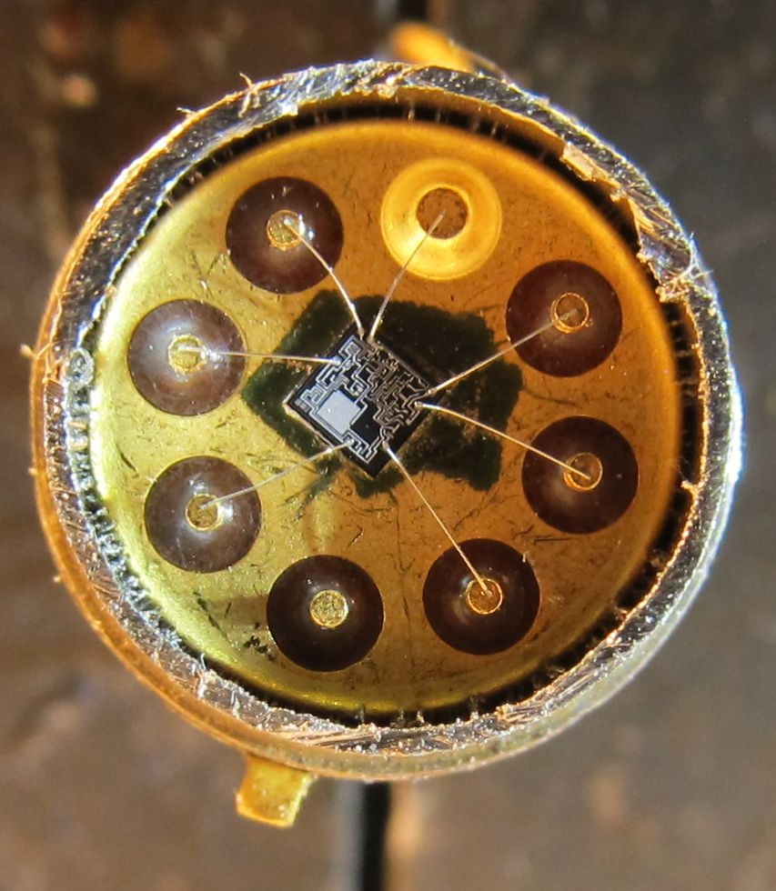
inside 741 - TO-5 Metal CAN
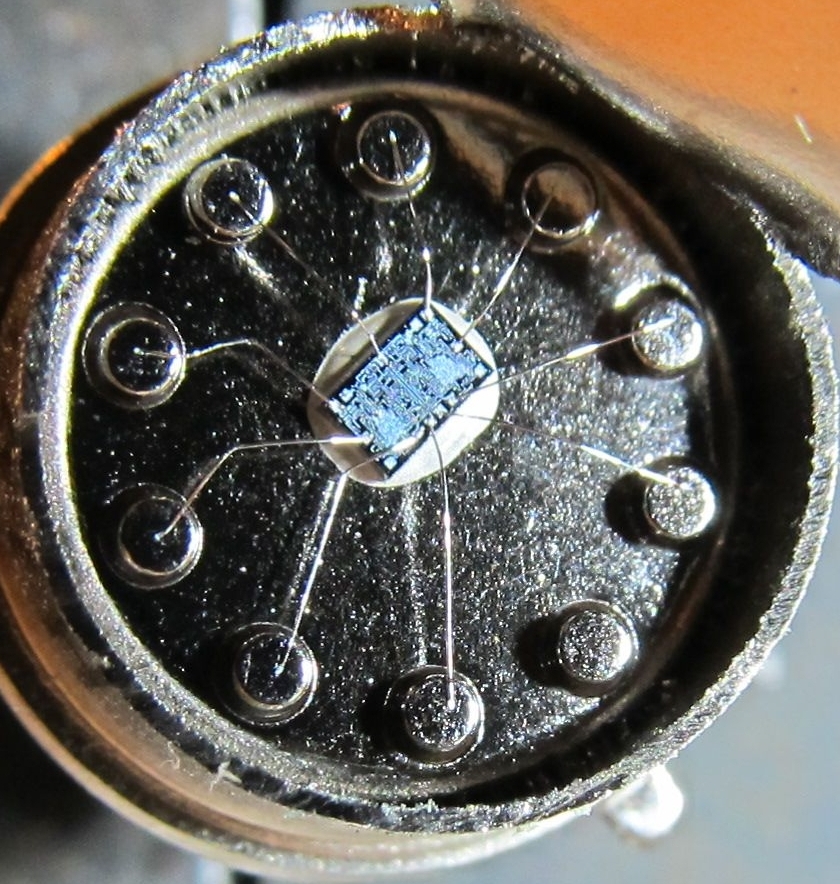
inside 747 - TO-5 Metal CAN
Comment
-
ไส้หลอดนี่ดูแล้วควรจำกัดกระแสมั๊ยครับ
ระหว่างปล่อยไปเกิน ให้หลอดดึงไปใช้เอง
กับ จำกัดกระแสเท่าที่หลอดต้องการComment
-
ความเห็นส่วนตัว
ผมว่า คุมแค่โวลท์ไม่ให้เกิน ไส้หลอดจะได้ไม่ขาด ส่วนกระแสปล่อยฟรี อยากใช้เท่าไหร่ก็มาเอาไป
ถ้าของเดิมคุมแค่โวลท์ แต่อยากรู้ว่าถ้าคุมกระแสด้วยจะได้ผลต่างแบบไหน ก็ลองใส่Rเพิ่มไปตัวนึงก็ได้ครับ แบบVoltage Regulators with Series Resistorsที่โพสไว้ข้างบนComment
-
> บทความของMIT --> Power-line Noise: How Series Filters Work
Most power-line treatment products depend upon series filters to correct AC line noise problems in the audio/video system. However, these series filters, unlike MIT's parallel filter system, have inherent flaws that make them ineffective at many vital frequencies in A/V use, and cause them to add more noise and distortions than they remove.
In this paper, we will explain how:
- series-filter noise rejection is ineffective in real-world systems
- series inductors create distortion products at audible frequencies
- noise that is supposed to go to "ground" is fed back into the circuit
- safety issues require the use of inadequate capacitance to reduce noise
- series-filter resonances actually create noise at audible frequenciesLast edited by keang; 9 May 2014, 13:04:53.Comment
-
"อิทธิพลของZobel" : มีผลต่อลักษณะเสียง ?
Photos/Schematic of Transparent Cables Found on the Internet
- วงจรภายใน

- รูปไส้ใน


อ่านรายละเอียดเพิ่ม > How to make a Transparent Audio Reference XL Speaker Cable
-----------------------------------------
มีหลายบริษัท ทำขายกันแบบไฮเอนด์มาก
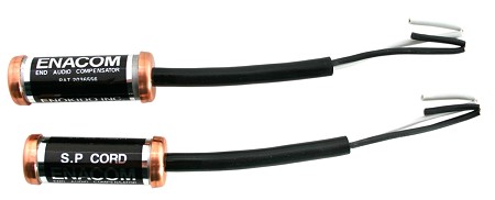
Enacom Speaker
Walker Audio

> เวป6moons รีวิวของเล่นประเภทนี้ : 6moons : the Ring A Sonic thriller


 Last edited by keang; 9 May 2014, 16:28:57.
Comment
-
-----------------------------------------
> wolfson : Impedance Compensation (Zobel Network) for Ground Referenced Outputs
Many Wolfson audio devices now have ground referenced headphone and line outputs, incorporating an innovative dual-mode charge pump architecture (Wolfson ?Class-W?) - to optimise efficiency and power consumption during playback.
The ground referenced output is achieved using an internal charge pump to power the headphone amplifier and means that there can be a direct connection between the Wolfson device output and the headphone load. This has several advantages compared to a VMID referenced output, including improved power consumption, better pop-click performance, and reduced overall cost of external components.
For stable audio performance with all types of headphone, a zobel network is required at any ground referenced output. If the zobel network is omitted, it is possible that charge pump switching frequency effects will affect audio performance.
This document describes why the zobel network is recommended and how the zobel network can work in the application.Comment
-
> Triode Gain Stage
The Common-Cathode, Triode Gain Stage
The common cathode, triode amplifying stage is the fundamental building block of all amplifiers, and must be fully understood before we have any hope of designing a whole amplifier.
Because this particular topic is so essential to understanding guitar amplfiers, and because most people reading this will be newcomers, I have decided to explain the matter in full detail. This article is also the first chapter from my book Designing Valve Preamps for Guitar and Bass, Second Edition
Click here to view the chapter (1.5MB PDF)Comment
-
DC Blocker
รูปวงจร DC Blocker ของเครื่องเสียงยี่ห้อ Crown และ Bryston ใช้

รูปวงจร DC Blocker แบบง่ายๆ แพร่หลายตามเวปDIY

-------------------------------------------
> Elliott Sound Products : Blocking Mains DC Offset
แนะนำให้เข้าตามลิ้งค์ เพื่ออ่านรายละเอียดของบทความทั้งหมด
Introduction
A varying DC offset on the AC mains is no longer uncommon. There are many ways that a DC offset can be created, with most being totally outside the control of those who have to try to eliminate it, or put up with the mechanical noise created in toroidal transformers.
There are a few older household appliances that can create a DC offset, although most are (probably) no longer permitted due to increasing problems caused by the DC component. This is more than compensated by various industrial processes, which for one reason or another manage to unbalance the mains supply sufficiently to cause problems.
Most of the time, the DC offset is transient - it appears for a short while, then goes away again. When it is there, toroidal transformers may complain loudly, by making growling or buzzing noises. It is important to understand just how this happens, and what can be done about it if it causes problems.
While the common solution found on the Net appears simple, there's a lot more to it than may seem to be the case. The operation is not intuitive, so while you may think that you know how it works, you could easily be mistaken.
It's also worth noting that DC is usually not a problem with toroidal transformers of 300VA or less. Their primary resistance is usually high enough that any DC will have little effect. With larger transformers (500VA and above), the DC resistance is usually so low that even a very small offset will cause mechanical noise due to saturation.
How DC Appears on the Mains
There are any number of different machines that can create a mains supply DC offset. Most will be totally outside your control, many DC "events" will be transient in nature, but one common theme applies - they will all load the mains supply asymmetrically for a period of time that ranges from a couple of cycles to minutes at a time. Figure 1 shows a typical (small) example that you may even have in your house - the transformer (shown within the dotted line) is your toroidal transformer. Many older hairdryers (and some heat guns as well) had a switch for "half power" that simply switched a diode in series with the mains. For a 240W element at 240V, that equates to a resistance of 240 Ohms (example only - actual power will vary widely).
If a diode is switched in series with the heating element, this reduces the voltage and hence the power (actual power will be almost exactly half). However, by half-wave rectifying the mains in this manner, there is an inevitable interaction with the mains impedance.
Figure 1 - Half-Wave Rectified Appliance, Transformer & Mains Wiring

The arrangement shown above assumes that the mains has zero impedance. Actual impedance is shown as R1, which varies from one house to the next. The value of 800 milliohms was chosen because this is what I measured at my workbench. Your mains may be better or worse than this.
After the asymmetrical load has done its job, a simulation shows the positive peaks of the 240V AC waveform reach 338.35V, but the (unloaded) negative peaks reach the proper value of 339.28V. This is a tiny bit less than the theoretical value of 339.41V because of the transformer load resistance and simulator resolution. The difference between the peak voltages is 0.93V, but the mean (average) DC voltage is -275mV. It is the mean value that appears as "DC" on the mains. It can also be measured, but to do so requires that one works on live components. This is not recommended as it is inherently dangerous. However, if you must (and PLEASE take extreme care), you need a 100k resistor and a 10uF non-polarised capacitor, wired in series. Connect this circuit across the mains (power off!), and connect a DC voltmeter across the capacitor. This attenuates the AC enough to prevent the front-end of the meter from being overloaded, and the DC voltage is easy to measure. Expect to see the DC vary around the zero voltage, with a normal variation of +/-25mV or so (typical - residential areas). The alternative method is to measure the DC across the diode/capacitor network in the circuit of Figure 3. Do not connect or disconnect the meter with the circuit live, and use alligator clip leads to make the connections.
With a half wave rectified load, the mean DC level is 275mV as described above - polarity is not important, because either polarity will be as bad as the other. If a transformer has a primary DC resistance of 2 ohms, there will be an effective DC current of 137.5mA in the primary. This is many times the current needed to cause the core to saturate during the negative half cycle of the AC waveform. Remember that with a toroidal core, saturation is a "hard limit". Because there is no air gap (intentional or otherwise), when the saturation limit is reached, inductance falls and current rises rapidly.
Tests were done using a 500VA toroidal transformer with very close to the example values given above. With 240V AC mains, 50Hz, 264mV DC offset created by DC injection (see Figure 6), and at no load, the current was seen to rise from 16mA to 218mA. The test was done at no load because this is the worst possible case. As load increases, the effective primary voltage falls - the voltage dropped across the winding's resistance is "lost" to the transformer. 264mV DC offset causes a current of 132mA DC in the transformer primary. This is probably the maximum offset that you will encounter in real life, although some areas may be worse. I have no data on this.
Use a Capacitor
Logically, using a series capacitor will block any DC. Capacitors cannot pass DC, so the waveform will re-centre itself to ensure that there is no offset. This happens regardless of how the DC offset was created, and is insensitive to waveform distortion. It's only when we do a few calculations that the real problem shows itself. Naturally, we want the lowest possible voltage to appear across the capacitor. We also want to ensure that a series resonant effect is not created where the capacitance and transformer primary inductance create a tuned circuit at (or near) the mains frequency. Such a circuit will appear as an extremely low impedance across the mains, and can generate voltages sufficient to destroy any capacitor (explosively!) and perhaps even the transformer winding insulation. Then the fuse or circuit breaker will blow, but the damage is done.
So, we need a capacitor (or a circuit) that will ...
- Handle the maximum current the transformer will draw (high ripple current)
- Drop the smallest possible voltage (large value of capacitance)
- Not cause series resonant effects
- Last for the expected life of the equipment
That's a tall order! Taking each point in turn, we can look at the likely requirements ...
Ripple Current - It may seem that we need to know the amplifier power rating, and also that of the transformer. We already know that the transformer will be subjected to considerable inrush current, both to set up the magnetising current and initially charge the filter caps. At this point, use of a soft start circuit (see Project 39) is highly recommended.
For the sake of the exercise, we'll use the 500VA transformer as shown in Table 1. Maximum long-term input current is ...
I = VA / V = 500 / 240 = 2.08A
From the DC perspective, the most critical region is at no-load. The saturation effects are greatly reduced when we are drawing significant current, so we will hopefully be able to simplify the circuit.
Voltage Drop - Now that we have the current, we can work out the required capacitance. Keeping the RMS voltage across the capacitor below 1V would seem like a reasonable figure, and I'd suggest that the maximum current of interest is around ? of the full load current - about 500mA. This means that capacitive reactance must be 2 Ohms or less. Remember that we can use Ohm's law to make these calculations - at least up to this point. Calculating the capacitance needed means that we use the capacitive reactance formula, suitably rearranged
C = 1 / ( 2 * pi * f * Xc ) where f is frequency and Xc is capacitive reactance
C = 1 / ( 2 * pi * 50 * 2 ) = 1,590uF
That's a fairly large capacitance, and can only be economically realised using an electrolytic capacitor. This raises a new quandary - electrolytic caps can operate for many years without a polarising voltage, but only at very low voltages. This means that the maximum voltage across the cap(s) must be limited, or they will fail. To be sensible, it will be necessary to use a pair of electrolytic capacitors, wired in "anti-parallel". A normal series connection with the two negative (or positive) terminals joined will also work, but reduces the available capacitance and maximises ripple current through both caps. Nonetheless, this may be preferable (see conclusion). The traditional way to limit the voltage is to use a number of high current diodes in parallel with the caps.
Series Resonance - The primary inductance can be calculated (close enough) by knowing the no-load current. All the primary current at no-load is the result of magnetising loss, and this is nothing more than that current which is drawn by an inductor when connected to the mains supply. The approximate effective inductance can be calculated, and it will generally be in the order of 40H or more. To save anyone the trouble, we have already determined that we need about 1,500uF, so series resonance can be discounted. The amount of capacitance is simply far too large to be able to resonate at 50Hz (or 60Hz) unless the transformer's inductance is impossibly small. However, it's still worth checking!
f = 1 / ( 2 * pi * ? L * C ) where f is frequency, L is inductance and C is capacitance
f = 1 / ( 2 * pi * ? 40 * 1,500u ) = 0.649 Hz
The resonant frequency of the network is well away from the mains frequency, so series resonance is not a problem.
Longevity - Inrush current can be very much higher than the nominal full power current, so the capacitor(s) require protection against over-current. The simplest has already been mentioned - the diodes that limit the maximum voltage across the caps will also limit the capacitor current. As current increases, so too does the voltage across the capacitors. The diodes will conduct if the voltage exceeds the forward voltage of either pair of the two series diodes. These diodes must be capable of withstanding the maximum peak current expected. This may exceed 50A for a brief period, and again, use a soft-start circuit!
Conclusion
Figure 8 shows the final (and recommended) design. While electrolytic caps can withstand a small reverse voltage (around 1V is typical), in the interests of longevity it is probably better to use the caps in series. Being in series, the capacitance of each must be doubled, and as shown the total effective capacitance is 2,350uF. Larger electrolytics can be used if desired, and a medium voltage rating will be required to ensure they can withstand the ripple current (this must be verified! ). Make sure the caps are well clear of anything that gets hot in operation.
Figure 8 - Recommended Design

While it is probable that using the caps in parallel as shown earlier will work reliably for many years, this is not something I can guarantee, because I've not performed any form of accelerated ageing process to the circuit. Not having used the circuit in any of my own equipment, I have no data either way.
The circuit and design processes described here will work for any size transformer. In most cases, the circuit shown in Figure 3 will be fine for any transformer from 500 to 750VA. DC stoppers are usually not needed in smaller toroidal trannies because their primary DC resistance is high enough to limit the (usually small) DC component so the DC has very little effect.
There is something to be said for the use of only two diodes in reverse-parallel, combined with larger capacitance (double the amount shown here). Voltages are lower, but the larger capacitors will be physically smaller because lower voltage parts can be used as ripple current is reduced. The critical component is the capacitor - that is the key to blocking DC.
It has been suggested elsewhere* that diodes have a forward voltage, and that is sufficient to block the DC component of the mains waveform. This is perfectly true for a low DC voltage by itself, but not with AC present at the same time. I tested the circuit using diodes alone and it does ... exactly nothing. The diodes are used to protect the capacitor bank, but it is the capacitor that blocks the DC - not the diodes. While the circuit may work with a small capacitance, it still has to be large enough to ensure that the normal idle current of the transformer cannot create a voltage drop such that the diodes conduct. The smallest capacitance that could be used with the circuit shown above is probably about 440uF (2 x 220uF caps), but this will be marginal. The caps may be unable to withstand the ripple current by the time the diodes conduct, and overall effectiveness is seriously diminished.
Additional tests I performed used only diodes (no effect whatsoever), and a 22uF and 1uF capacitor, and both of these were completely useless. Actually, they were worse than useless, by actually creating a DC offset! Without a very detailed examination, it appears that the small capacitance is only capable of averaging the slightly different forward voltages of the diodes, resulting in a few millivolts of offset. Because the cap is not big enough to maintain the AC component to a value well below diode conduction voltage, this small DC voltage then becomes an offset. With 1uF, transformer idle current rose to about 25mA without any external DC, and was 170mA when DC was added (same setup as used for all other tests). Idle current was a little less than this with the 22uF cap, but not by very much.
It's worth noting that the mains "DC" observed (measured across the diode/capacitor network) varied by about ?25mV worst case - at least while I was watching!. However, this was measured in a residential area, and there is no doubt that much higher voltages occur from time to time. I expect that a circuit that has been tested to work with over 250mV as shown here will be more than sufficient for most installations.
The circuit as shown will also work perfectly with 120V 60Hz, but it would be wise to increase the capacitance (double the value shown here). Although the caps will work better with the higher frequency, the transformer idle current will be almost double that of a 220-240V transformer.
Safety
Electrical safety is of utmost importance with a circuit such as that described here. Never rely on the electrolytic capacitor outer plastic sleeve for insulation. All parts must be meticulously mounted, with special consideration to personal protection from live components and separation of all low voltage conductors from anything at mains potential.
Ideally, the entire circuit will be afforded an earthed metal cover plate. This protects against accidental contact, and ensures that should a capacitor choose to explode, it's intestines will be confined to a small area, rather than scattered throughout the amplifier chassis.
Regardless of whether the circuit is installed in the active (live) or neutral conductor, the insulation requirements do not change. There is no guarantee that the neutral will always be at earth potential. A mis-wired mains lead, power board, extension lead or power outlet will all make the active become the neutral and vice versa. Because of this, you must allow for the worst case and insulate accordingly.
While testing your new DC Blocker, you must use insulated alligator clip leads for your multimeter. All connections must be made with power off. The clip leads allow you to make connections that don't rely on you holding probes in position. A slip can cause a lot of damage!.
If at all possible, use a Variac to power the circuit for the first time. This allows you to monitor everything and power can be removed before any damage is done if you made a mistake. If a Variac is not available, use a 100W lamp in series with the mains lead. Ideally, the secondary windings of the transformer should be disconnected while you are testing.
-------------------------------------------
ใครทำตัวนี้ไว้ใช้งาน อย่าลืม คำนวน ค่าทนกระแสของไอโอดและค่าC ให้เหมาะสมกับโหลดที่เอาไปต่อใช้งานด้วยOriginally posted by dracoV
-------------------------------------------
เวป-กระทู้ ที่มีคนทำ DC Blocker
> diyAudio - Glen B : DC blocker diode/cap orientation
> diyAudio - mhouston : DC blockers and mains filters
> OAMLabs F45mk2 Mains Filter and DC Blocker
> Mono and Stereo High-End Audio Magazine : AC/DC ... or a Highway to Hell
> Tweakers' Asylum : Naive questions re d-i-y
> XtremePlace - vertigo_ blues : Dc blocker
> The Art of Sound - HighFidelityGuy : DIY DC blocker?
> nuummie : DC Filter ที่ผมทำ
> nuummie : DIY DC Blocker สำหรับไฟ AC
> htg (too ninja) - Goda Takeshi : การใส่ capacitor ในปลั๊กกรองไฟ
> ocz - osxp : หน้า287 #5725
รวมรูป วิธีการทำDC Blocker จากgoogle
> google search : dc blockerLast edited by keang; 13 May 2014, 14:15:02.Comment
-
DC Blocker ผมทำไว้ในกระทู้ Club Xonar DS หลายตัวเลยครับ
เริ่มตั้งแต่ใช้ C คู่เดียว จนถึงหลายๆ คู่

ขอเอาตัวใหญ่ที่ใช้อยู่กับ AVR ตอนนี้มาลงเลยละกันครับ
รายการอุปกรณ์ที่ใช้ และแหล่งซื้อ งบประมาณ 1พันบาท
C 10,000uF 63V 8 ตัว (ใช้ Samwha ตัวละ 65 บาท : digitclass.net)
Bridge Diode 50A 1 ตัว (55 บาท : digitclass.net)
สายไฟแข็ง Thai Yazaki 4.0mm (เมตรละ 22 บาท : ไทยวัสดุ)
แผ่นปรินท์เอนกประสงค์ (30บาท : อมร)
กล่องกันน้ำ Leetech (155 บาท : Global House)
ปลั๊กผนัง Panasonic (110 บาท : ไทยวัสดุ)
ขั้ว IEC Schurter (43 บาท : avbestbuy.com)
วงจรก็เหมือนวงจร DC Blocker อย่างง่ายทางด้านบน ที่ใช้ C 2ตัว Diode 1ตัว
ต่างกันแค่ใช้ C หลายคู่ต่อขนานเข้าไปแค่นั้นเอง

การเดินสายด้านหลัง


เอาลงกล่อง

ใช้งานจริง

ผลที่ได้เสียงจะสะอาด ชัดเจนขึ้น
แรกๆ อาจจะแข็งๆหน่อย แต่พอพ้นเบิร์นซัก 100 ชั่วโมงขึ้นไป จะใสพริ้วขึ้นกว่าตอนแรกๆ
แนะนำให้ลองทำกันดูครับComment
-
ขอบคุณครับ ใส่หน้าแรกเรียบร้อยแล้วครับ
---------------------------
DC Blocker : มีวิธีคำนวนครบเลย
> DC-Filter for the 230V/AC Power Connection

วงจรDC Blockerที่ใช้งานจริง จะเป็นรูปขวาล่าง / รูปซ้ายล่าง คือ แบบใช้บริดจ์ไดโอด เพื่อความสะดวกในการหาไดโอดวัตต์สูงมาใช้งาน
 Last edited by keang; 16 May 2014, 13:31:46.
Comment
-
Use a Linear Potentiometer to Create a Nonlinear Transfer Function for Audio Volume ControlOriginally posted by dracoV
Adding a series resistor to the circuit (R1 in Figure 2a) yields an entirely different result. Now this circuit's transfer function more closely resembles a logarithmic curve and is characterized by the equation VOUT = VIN(RB/(R1 + RB)). By varying the value of R1, which in this case is 10k?, the "pseudologarithmic" transfer function can be customized to meet the actual needs of the circuit. A graph of the transfer function is shown in Figure 2b. One possible drawback to this circuit, as compared to a log-taper digital pot, is that VOUT can only approach the full-scale value of VIN. VOUT cannot reach VIN. Therefore, there is some loss of the output's dynamic range; the magnitude of that loss depends on the value chosen for R1. Using a log-taper digital pot, however, limits the response to that particular pot's specifications (1dB/step, 2dB/step, etc). There are trade-offs for both topologies, depending on the specifications needed.
Figure 2. Pseudologarithmic-response (a) circuit and (b) plot.
 Last edited by keang; 13 May 2014, 15:07:25.
Comment
-
ดันชอบกระทู้นี้มากๆComment
-
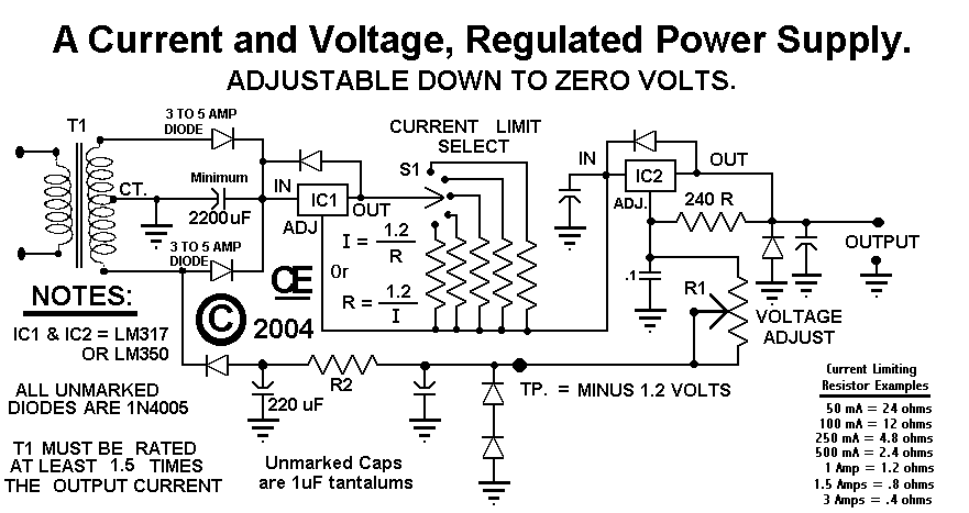
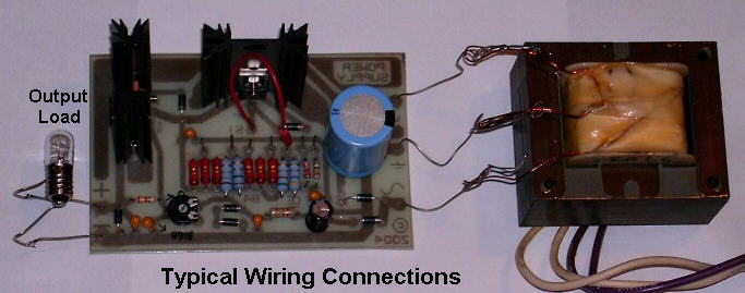
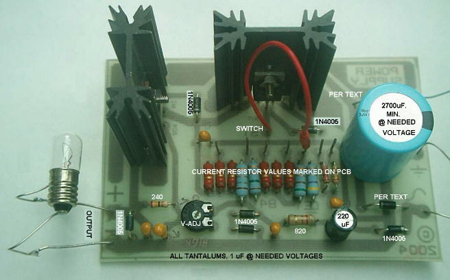
Boot Camp for Capacitors-in-Training ... คลิก
Here is an answer to audio capacitors that require an inordinate amount of break-in time before they sound even listenable: the cap-rack!

The concept is to build a device that you can easily plug components in and out of from stuff you probably have lying around already. The cap-rack keeps the capacitors polarized while subjecting them to large charge-discharge cycles. A few days is guarenteed to break in even the most stubborn of exotic capcitors!
วงจร

You need a small transformer like those found inside any generic power supply. The AC output should be about 9 V, so the innards of a 12V - 14 V, 500 mA power supply would be ideal. Attach an AC cord to the input side of the transformer, being careful to tape or apply heatshrink over any exposed wire.
If you scrounged the transformer from a DC power supply, chances are the bridge rectifier diodes are still attached. If so, leave them there; if not, attach a single 1N4001-or-bigger diode on as shown on he circuit.
Find a resistor rated at least 2 W, 5 W is better. Anything bewteen 100 and 1000 ohms is fine. Insert across the output as shown.
Add a screw terminal strip and mark the positive terminal for easy identification. A large terminal strip can be wired to accept several capacitors at once.
Attach the capacitor, plug the transformer into a wall socket and try and forget all about it for a week. Then come back and wire those great sounding, fully broken in capacitors into your audio system!
I built this device to break in the Black Gate electrolytic capacitors I planned to use in the cathode bypass circuit of my tube amp. The values were 10 ?F / 50 V and 100 ?F / 50V. Black Gates are the most notorious example I know of components that sound bad until a long break-in time has expired.Comment
-
พอจะมีใครทราบมั้ย
ที่งัดพลาสติค (ที่ไว้งัดเปิดขอบตอLCDหรือ พวกกล่องพลาสติคที่เป็นสลักล็อค) นี้หาซื้อได้ที่ไหนเหรอครับComment
 Tweet
Tweet


Comment