Update (2/1/14): Added the ADM7150/ADM7151 which is now at the top of the pack.
Update (01/29/13): Revised the noise density numbers
Update (8/27/12): Added the new TI TPS7A4700 regulator to the table. This device can source up to 1 A of current and ranks on top of the list. Also please ignore the noise density numbers, I need to revise them. Look at the RMS noise values.
The table below compares the noise level of some regulators used in current DIY modules vs a new breed of regulators that are used in portable consumer devices such as cell phones.
Just like phase noise in clocks, it is difficult to compare noise values among linear regulators because there is no common ground in specifying noise figures. Some companies report noise density, others RMS V noise, and yet others % of Vout. The frequency range for the reported noise figures also varies from company to company. Thus it is required to convert spec numbers to a common measuring unit. I chose to convert everything to ?Noise Density? in nV/Sqrt(Hz) numbers.
In order to understand the relationship between RMS noise and noise density, you can watch this video tutorial :
The noise density numbers are a good approximation and calculated in accordance to the instruction presented in the video above. They have been further normalized to a bandwidth of 100KHz. (I?ve redone the calculation and this time is correct). The number represents the ?tail? of the noise spectrum which is typically a flat line.
The first two rows are application notes indicating the noise density value of the noise floor. AN51 is a discrete design using a ZETEX voltage reference. LM723 is an old part used in older designs. Newer monolithic designs have the added advantage that they are also very low dropout (LDO).
The comparison suggests that whether using a discrete design or state of the art monolithic regulators, we are very close to the measurable noise floor (~14 nV seems the best regulators so far?).
For the diyer, these devices are very small and maybe very hard to solder, especially the micro SMD bump package.
As previously discussed, the noise density numbers are an approximation assuming that it is ?flat? throughout the bandwidth of interest. The area under the noise density trace is the RMS noise figure. So basically, if we assume a square area and a bandwidth of 100 KHz
< RMS Noise = Noise Density X SQRT(100,000) = Noise Density X 316 >
Note: the second noise figure for the LM317 comes from TNT-Audio [link]. There, it is measured at 250 uV for the ~20Khz bandwidth.
- The 6922 is designed to handle higher power than the 6DJ8, and for longer life. Otherwise, they're the same. A 6922 will work in a 6DJ8 circuit. The converse is not always true, as a circuit that pushes a 6922 hard may overload a 6DJ8. Usually they are interchangeable.
- In order of longevity and toughness of the tubes the order goes like this: 6DJ8 - 6922 - 7308. I think it is something like 2500 hour longevity for the 6dj8; 5000 for the 6922 and about 10000 for the 7308.
Other than that they are the same exact design and pinout. The higher the longevity the more the tube can handle voltage wise, so replacing a circuit specifically designed for a 7308 tube with a 6dj8 will DRAMATICALLY reduce your tube life. You might only get a few hundred hours out of your 6dj8 in this case for example.
- these were the best sounding tubes of the entire 6dj8/6922/7308 family. I bought two pairs of early 60's tubes, the ones with the dull grey all around the middle section, and thought that they were absolutely incredible sounding tubes. A little dry sounding, but very detailed and nice. I had mine cryo treated and that gave them a little longer life and a slightly different sound. (In a good way different.)
- If you go to Audio Asylum to the FAQ section and look under Joe's Tube Lore, http://www.audioasylum.com/scripts/d...oes-tubes.html you will find a good bit of information regarding these as well as other small signal tubes. Also Vacuum Tube Valley http://www.vacuumtube.com/ publishes a magazine and under back issues you can order Issue 7 from Spring/Summer 1977. The lead article is "The 6DJ8 and other Frame Grid Tubes" which also gives you a good overview of what was made and the differences between the different tube types. ServinginEcuador summed it up well though in terms of the evolution. The latter tubes (7308) were made to be more durable than the earlier versions.
- 6DJ8 / ECC88 is the "standard grade" of this family. They normally have steel pins.
- 6922 / E88CC is a "premium grade" version of the 6DJ8. Most have gold plated pins, but many Sylvania manufactured 6922's have steel pins (a few Sylvania's are gold pin).
- 7308 / E188CC is "generally the highest quality tube" in the 6DJ8/ECC88 family. Most have gold pins. Sylvania's are steel pin. They are designed with low microphonics and low noise. Sections are usually pretty closely matched.
- 7DJ8 / PCC88 These are "7 volt filaments" which were designed to be used in series string circuits. However, they work well in standard 6DJ8 circuits and can generally be used as direct substitutes. You can some some money using these.
- CCa This is a "special version of the 6922 / E88CC" which is usually only found as Siemens or Telefunken. These are very rare tubes and usually not in stock. But as for everything else, call or email to make sure.
6DJ8 :
This is the standard incarnation of this tube. It was made both in the USA and in Western Europe. GE and Sylvania both made USA versions, and are fairly good quality. The GE tubes have an RF shield sprayed on inside the glass, making the inside look dark. This is NOT an indication of a burned out or used tube. RCA tubes were often made by either Mullard or Amperex in Britain or Holland. The most popular NOS vintage tubes are those made by Telefunken, Amperex, Siemens or Mullard, and are usually also labelled ECC88. See the next paragraph for this description.
ECC88 :
This is the European designation for the 6DJ8 type tube. It is the same tube as a 6DJ8 and often the tube has both type numbers on it. The popular vintage tubes here are those by Telefunken, Amperex, or Mullard. The Telefunken are said to sound the best, and are the most difficult to find of all of these brands. All Telefunken tubes have a tiny diamond shape molded into the glass on the bottom, and have a very chalky ink on the surface which often is partially wiped off. Beware! These tubes are being reproduced in China, and look like the real thing, complete with diamond mark. The tipoff is the label: the fake labels will not wipe off.
The Amperex can be found with a white label and the treble clef logo (rare), the Bugle Boy cartoon tube logo, Amperex in white ink, and the orange world logo. The orange world logo is the newest, and can be found in both standard "L" bracket top getter, and the rarer (and said to sound better) "A" frame top getter. The A-frame looks like a little metal "A" holding up the getter element on the top of the tube internal structure. I have also seen the A frame getter on some Mullard and Genalex (G.E.C.) tubes. The Bugle Boy is the most popular, almost to being a "designer" label, which has driven the price up and supplies down. See note below about Bugle Boy 6DJ8 tubes. I believe any of the Amperex / Philips Holland 1960s and 1970s 6DJ8 tubes are excellent, no matter which one you use. The tubes made with the plain white label (Amperex, DuMont, Hewlett-Packard, Beckman and others but all labelled "Holland") were made in the same factory as the Bugle Boy tubes and sound the same, but are often bargain priced due to low demand. Beware! The Bugle Boy tubes are being reproduced today! The box of the new tubes is even an identical green-and-yellow like the original, but it says "Bugle Boy" on it, and some even show the cartoon tube on the box. Original Amperex tubes NEVER had the words "Bugle Boy", or the cartoon tube, on the box. The Bugle Boy moniker is a slang name that audiophiles coined for the the little cartoon tube on the tube's label. The new tubes have fooled even some seasoned audiophiles! These are junky Chinese made tubes with the old label. The company vending them says they have the original burn-in racks from the old Holland factory. Big deal!! The old burn-in racks are not going to help a crappy tube. Stick with the vintage tubes while you still can!
Mullard 6DJ8 tubes are excellent as well, but are more difficult to find. They often made 6DJ8 tubes for other labels, like RCA, Zenith, and other USA brands. They have several seams molded into the top of the tube.
6922 :
This is one of two premium versions of the 6DJ8 tube. First of all, it is the same tube as the 6DJ8, and will work wherever a 6DJ8 is needed. It has premium features such as low noise, low microphonics, and usually a longer lifespan. Sylvania made a version that is JAN military spec without gold pins. Amperex made all of theirs with gold plated pins and most have the PQ shield logo, standing for Premium Quality. See note below about Amperex 6922 and Bugle Boy tubes. Some of the later gold pin Amperex have the orange world logo. I have seen both orange and white PQ logos. Some of the early versions also have a number etched into the glass, like the 7308 tubes. These were also made for other manufacturers, and will have that makers name labelled in white, but these are the same gold pin tubes. Amperex opened a factory in New York to make these for the US military (since the government contract specified only USA constructed products) and cranked these and 7308 tubes out. A "made in U.S.A." Amperex tube is not a fake! In fact, these tubes are really excellent. A few were made in Holland for non-military industrial use, but these are rare. Also rare are the "pinched waist" versions of this tube. This is actually a molding flaw which made the glass bottom slightly fatter around the outside than the rest of the tube, and the center of the tube actually dips inward and touches the metal elements inside. Clients report these are incredible sounding tubes, and the upward spiral of prices for the rare pinch waist types seem to bear this out. Finally, Philips (the parent company of Amperex) owned a number of tube brands, and many were never seen outside of Europe. Most were actually made in the same Heerlen, Holland factory that turned out the Bugleboy 6DJ8 and PQ 6922 Amperex. Watch for tubes labeled E88CC with brands like Valvo, R/T, RTC, Miniwatt, Dario, Philips, and Adzam. These tubes are identical to the Amperex PQ and Philips SQ (Special Quality) types more often found in America, and are perfect if the Amperex is not available. Also rare in America are these same brands made at the Philips-owned Mazda factory (La Radiotechnique) in Suresnes, France. These usually have a capital "F" in the second line of the date code. They are sweet like the Holland tubes, with a bit better detail and punch at the top end, and still have nice balanced warmth. We are one of the very few worldwide tube dealers to offer these rare NOS French Philips tubes.
RCA 6922 tubes were made by Siemens in Germany, and also have gold pins. These are great tubes, but are not as plentiful. Since the military and some large industries (Tektronix) bought the Amperex made tubes in huge batches, that is what is on the surplus market today.
E88CC and E88CC/01 :
This is the European equivalent to the 6922, and is a quality step up from the standard 6DJ8 or 7DJ8. Telefunken made a fantastic version of this tube, complete with gold pins. Other vintage brands are available, but Telefunken, Philips, Siemens and Mullard are all I have ever seen in several years of tube hunting. Virtually all European brands have gold pins. Most are factory screened for tight internal matching and low noise. The E88CC/01 type (I have only seen these in Mullard brand) has even more factory testing. It is rather like a Cca type tube, with essentially military specs. It's the same as the CV2493, some have both types on the label. The /01 type is rare and worth seeking out if you like the warm British sound. There are some types out there, like "Golden Dragon" just to name one, but these are recent manufacture Chinese tubes, and can't hold a candle to the quality of the Telefunken or even any of the vintage 6922 types. There are also some nice USA made military and industrial types available with either gold or standard pins, and even these sound better than the current production tubes, and are usually priced the same or less.
CV2493 :
A rare military version of the E88CC/01. Some have both types on the label, some only the CV2493. This can be considered the British or Dutch version of the German Cca. Very low noise, carefully matched triodes, and these are batch tested to meet military specs. Usually only available in the Mullard brand, I have seen some with the Amperex Heerlen, Holland factory codes on them, even though they have the Mullard label. Scarce in the USA, and not found in the later Yugoslavian versions like the more common CV2492. It is possible only the UK and Holland made these tubes and were discontinued by the mid 1970s. Probably one of the best choices for tube microphones and mic preamps, or any other high gain, low noise use.
CV2492 :
This is a European military (usually British) version of the 6922 / E88CC type vacuum tube. Unlike the US military version, these tubes were never made in the USA. Most of the older examples were made in either the Mullard Mitcham, UK factory, or the Philips/Amperex Heerlen, Holland factory. These are fine tubes that have passed various demanding military specification tests regarding ruggedness, heat and shock resistence, and heater life. Like their civilian/industrial counterparts, they have the four molded seams on the top, heavily plated gold pins, a halo top getter with a splatter shield below it (with slight raised indentations at the 3 and 9 o'clock positions on the shield), and the standard Mullard/Philips factory date codes printed near the bottom of the glass side. Care must be taken, however, when buying these tubes if they are merely identified as "CV2492" tubes. These tubes were made well into the 1980s, and later examples are not as valuable or as desirable as the earlier varieties. Later versions were made in the former Yugoslavia and then in Russia. The Yugoslavia versions can be spotted by their lack of gold pins, and the halo getter mounted low, almost touching the splatter shield. The Russian versions are even easier to spot, as they have a fatter glass bottle, a top mounted cup shaped getter, no top mold seams, and sharp pointed pins which may or may not be gold plated. These are not bad tubes, but should only be worth one half to one fourth of what the UK or Holland made tubes are retailing for. Give the CV2492 a try, the older versions are sweet sounding and long-lived, and are a step up from the garden-variety 6922 / E88CC, and prices are generally a little lower.
E188CC :
A bit rarer than the E88CC, the E188CC is usually found labelled as such by Siemens or Telefunken. Amperex and other makers (Sylvania for example) used the industrial 7308 marking, Amperex Holland and France used the E188CC label. It is basically the European equivalent to the 7308. The E188CC has gold pins, and is near the top of the 6DJ8 food chain. The Siemens version from the 1960s is quite rare, and is rated by many audiophiles as a jewel on par with the best Cca tubes, or the cryo-treated 7308s. It has low noise to the vanishing point, and a wonderful, airy top end and soundstage. This early version Siemens has a small halo top getter, and is labelled E188CC in white ink. Versions made in the Philips Holland plant are similar, and have the SQ logo. If you find some, grab 'em while you still can! Finally, Philips (the parent company of Amperex) owned a number of tube brands, and many were never seen outside of Europe. Most were actually made in the same Heerlen, Holland factory that turned out the Bugleboy 6DJ8 and PQ 6922 Amperex. Watch for tubes labeled E188CC with brands like Valvo, R/T, RTC, Miniwatt, Dario, Philips, and Adzam. These tubes are identical to the Amperex PQ and Philips SQ (Special Quality) types more often found in America, and are perfect if the Amperex label is not available. Also rare in America are these same brands made at the Philips-owned Mazda factory (La Radiotechnique) in Suresnes, France. These usually have a capital "F" in the second line of the date code. They are sweet like the Holland tubes, with a bit better detail and punch at the top end, and still have nice balanced warmth. We are one of very few worldwide tube dealers to offer these rare NOS French Philips tubes. Finally, watch for Siemens or Telefunken German made E188CC/7308 tubes, most having the E188CC label in white, with the Telefunken having the distinctive diamond shape in the bottom glass. Siemens are usually more plentiful, and a huge savings over their Cca tubes.
7308 :
This is probably the ultra 6DJ8 type tube commonly available. It has all of the features of the 6922, but the triode sections are also matched to each other, and the tubes all fit within very tight specifications. Therefore, any 7308 should match any other 7308 within the same brand. The Amperex versions were again made in New York, complete with gold pins, and often have a number etched into the side of the glass. Amperex made these for industry as well as the military. The Amperex versions have the PQ label, the military type usually is labeled "USN-CEP", but I have seen versions made for Stromberg-Carlson and Hewlett-Packard, with white ink labels. These all had the numbers etched into the glass, and all are the same tube. The USA made military white label types have been rated "Best of All", over other 7308, 6922 and even Cca tubes, in several well-documented 6922/7308/Cca listening tests. Therefore this particular type is becoming scarce and prices are rising. There were a few of these made in Holland, but most were made in the USA, therefore the Holland tubes are RARE and usually command a higher price. The Holland PQ versions have the PQ with stars on either side of the letters, and the words "Premium Quality", where the USA types have the PQ inside of a shield logo. Again, there are some nice vintage USA made standard pin military and industrial types available from Raytheon and Sylvania, just to name a few, and these are quite good at a price currently far below the European vintage labels. Finally, Philips (the parent company of Amperex) owned a number of tube brands, and many were never seen outside of Europe. Most were actually made in the same Heerlen, Holland factory that turned out the Bugleboy 6DJ8 and PQ 6922 Amperex. Watch for tubes labeled E188CC with brands like Valvo, R/T, RTC, Miniwatt, Dario, Philips, and Adzam. These tubes are identical to the Amperex PQ and Philips SQ (Special Quality) types more often found in America, and are perfect if the Amperex label is not available. Also rare in America are these same brands made at the Philips-owned Mazda factory (La Radiotechnique) in Suresnes, France. These usually have a capital "F" in the second line of the date code. They are sweet like the Holland tubes, with a bit better detail and punch at the top end, and still have nice balanced warmth. We are one of the very few worldwide tube dealers to offer these rare NOS French Philips tubes. Finally, watch for Siemens or Telefunken German made 7308 tubes, most having the E188CC label in white, with the Telefunken having the distinctive diamond shape in the bottom glass. Siemens are usually more plentiful, and a huge savings over their Cca tubes.
E288CC :
This unusual tube is basically a 7308 / E188CC in a slightly taller bottle. The filament current draw is also slightly higher but for most applications it is plug and play compatible with the 6922, 7308, Cca, or even the 6DJ8. Physical space is a consideration, since the tube is about one-half inch taller than the rest of the tubes on this page. It features gold pins, factory screened triodes for low noise, 10,000 heater life, and all the other great features that make the 7308 and the Cca such high-demand tubes. Since it is a relative unknown, the prices are about the same as good 6922 tubes, and far below that of most 7308 or Cca types! I have only seen this tube in Valvo, Telefunken, or Siemens brands. Worth giving a try if you want the best but cannot afford the soaring costs of NOS 7308 or Cca tubes.
Cca :
Whew, these babies are so scarce there isn't even much info out there about them! Mentioned by audiophiles, usually in a reverent whisper, these gold pinned gems are about as good is it gets in 6DJ8-land. Matched triode sections, low noise screening, 10,000 hr. heater life expectancy, carefully controlled frame grid winding, low microphonics......the list goes on and on. This is regarded as one of the most detailed and three-dimensional sounding tube ever made in this family of tubes. Most of what is available is Siemens or Telefunken made, although there are a few very rare examples of Philips or Amperex Holland made out there. Since this was a tube made specifically for the German goverment and military, all that I have seen carry a German brand label, even those made in Holland. Even rarer are the Holland made Cca tubes with the pinched waist indented glass midsections, said to be the most sonically "3D" tube ever made, of any type. Finding these is akin to finding a 1795 gold piece in your attic! I don't believe there were any of these Cca tubes made in the USA. Awesome audiophile tubes!
6H23 :
This is a Russian made equivalent to the 6922 or E88CC, but will work in place of any 7308 or 6DJ8 type as well. Ordinarily the Russian tubes are just not of a high enough quality to go head-to-head with NOS German, Dutch, or UK tubes. These are a possible exception. The so-called "rocket logo" type from the 1970s and early 1980s seems to hold it's own against NOS tubes costing 3-4 times as much. These NOS Russian rockets have been critically acclaimed in several online discussion boards for their detail and smoothness. At current prices, these are about one-third to one-fourth the cost of NOS Western Europe types, and so their value is enhanced even more.
7DJ8 / PCC88 :
This is an unusual tube that must have had a limited range of specific uses. It is virtually identical to the 6DJ8 except for the heater rating, which is 7 volts. I have seen Siemens, Valvo, Telefunken, Philips, Ultron and Matsushita (Japan) brands of this tube. It probably makes a good sub for the 6DJ8 and may last longer due to the higher voltage heater. Some are labelled with only the "PCC88" and others have both types listed on the label. All seem to be good quality. The Japanese factory was set up by Mullard, and these tubes even flash orange at the bottom of the filaments when first energized, like most European triodes do. Most of the European types were made at the Munich Siemens factory, the Hamburg Valvo factory, the Heerlen Holland Amperex Factory, or the Blackburn, UK Mullard factory. These sound just like the best 6DJ8 tubes, the German tubes being mostly neutral, and the Dutch and British tubes having a touch of midrange warmth. Watch for the very rare D-getter types and even rarer pinch waist types, often at bargain prices (compared to 6922 types in these categories) when you can find them. You may want to try a 7DJ8 for the longer heater life in a 6.3 volt circuit, and the lower price!
DC heater supplies :
Properly designed DC supplies do not cause hum since the stray current between filament and cathode is unchanging. However, DC supplies nearly always need to be voltage regulated or they can cause even more noise than an AC supply! (although simple rectification to DC does sometimes work).
Simple, three-pin voltage regulators usually require an input voltage that is at least 2.5V above the output voltage in order to work. Most regulators cannot handle more than about 1A of current on their own, so it is quite common to operate the comparatively low current pre-amp valves from a simple regulator, and run the current-hungry power valves from an ordinary AC supply, since they are less prone to hum anyway. Higher-current regulators are available, however, at slightly higer cost. The regulator must always be fixed to a suitable heat sink.
The simplest and most popular range of fixed-voltage regulators is the 78xx series. A 5V regulator can have its output raised to ~6.3V by elevating its ground terminal by 1.3V; the voltage drop across a pair of silicon diodes is almost perfect for this. Higher voltages could be obtained by using zeners instead, but the input voltage must always be at least 2.5V higher than the output. 6V regulators do exist, but are not as commonly available as the 5V versions.
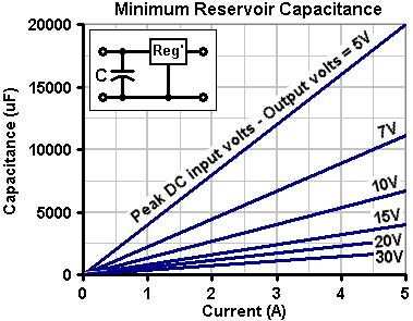
In the circuit below, the 7805 regulator can provide up to 1A on its own. If more current is required, the transistor can be added to provide up to 5A max (it too will need a heat sink). The 1uF capacitor must be positioned very close to the regulator. It does not have to be tantalum, a ceramic will do at a pinch. A normal 6.3V transformer winding will NOT provide sufficient voltage after rectification to power this circuit.
Layout / lead dress :
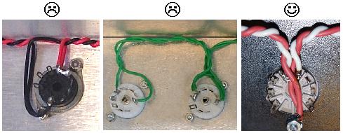
The lead dress of AC heater supplies is very important for noise reduction. The AC heater wires will have significant EM radiation and should therefore be routed well away from all signal wires, and are usually tucked into the corner of the chassis. The wires should either be made from twin cable (bell-wire) or better still, should be made by twisting the wires neatly and tightly together. In this way the wires are kept perfectly parallel and close to each other, which increases opposing field density and encourages the radiated fields to cancel out. Loosely twisted wires are no use at all.
When heaters are wired in parallel; power valves should be first in the heater chain, followed by driver valves, with the input stage being last in the chain. This keeps current, and therefore radiated fields, at a minimum around the most sensitive stages of the amp. Even better is to run the pre-amp and power-amp sections from separate heater chains. If signal wires must cross the heater wires, they should do so at right angles.
Valves in push-pull or in balanced stages (such as long tailed pairs using separate valves) should have their heaters wired in phase. Any noise induced will then be common mode and rejected by the stage (mostly). Valves in parallel single-ended stages should have their heaters wires out of phase for mutual cancellation. Using two different colours for the heater wires will make this easier.
The common pre-amp valves (ECC83 / 12AX7 etc.) when run from a 6.3V supply, should be wired from one side only [see right], not by looping one heater wire all round the valve socket, which would create a hum loop and cause excessive interference noise (though many amp makers DO make this mistake and get away with it). The wire twisting must be kept very tight right up to the socket, where it matters most. Their pin arrangement is also deliberate, so that the main heater pins (4 and 5) can be orientated towards the chassis wall, allowing heater wires to be run along the wall away from any other sensitive signal wiring.
A universal heater supply ?
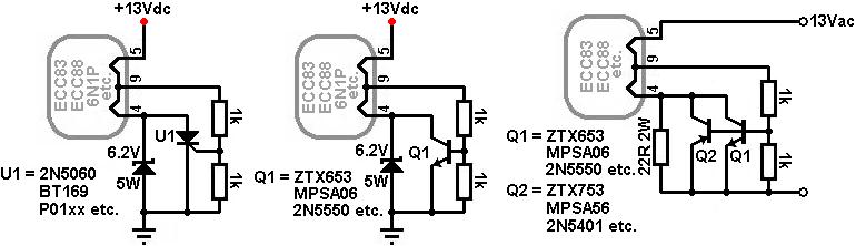
Everyone likes tube rolling, but it is somewhat dissapointing that the only valves which are compatible with the ECC83/12AX7 pin-out are the ECC81/12AT7, ECC82/12AU7 and 12AY7. But there are many other valves which conform to the more standard pin-out such as the ECC88/6DJ8, ECC85/6AQ8, 6N1P, 6N2P and other Russian types. Although we could provide a switch at every valve socket to select between the two pin-outs, it would be nice if we could just plug in any type without any changes. The following circuits are designed to allow this, but automatically detecting which type is inserted. All these circuits operate the ECC83 types from 12.6V. If an ECC88 type is plugged in, however, a zener diode is placed in series with the heater to limit the heater voltage to about 6.3V.
Each circuit uses pin 9 on the valve socket as a control port. If an ECC83 is plugged in this pin goes positive, causing the SCR (U1 left-most circuit) or NPN transistor (Q1 middle circuit) to turn on, shorting out the zener. There is still a small drop across this device though, which is why the supply voltage is shown a little higher than 12.6V (it will probably be a little higher in this mode anyway, since an ECC83 only needs 150mA heater current).
When an ECC88 type is plugged in, pin 9 is connected to nothing, so U1 or Q1 turns off, and current is steered into the zener diode, which drops roughly half the supply voltage across itself.
For AC heater we simply use an NPN/PNP pair connected in parallel (Q1/Q2 in the right-most circuit). A triac or even an opto-triac could be used too. However, zener diodes can't be used in the same way for AC, so a resistor is used instead. Unfortunately this means that some of the Russian valve types (notably the 6N1P) can't be used, since they require up to 600mA current which causes too much drop across the resistor. Most European/American types and the 6N2P should be ok though. Another disadvantage of this design is that it is not balanced, so a humdinger pot will probably be needed to null any heater hum. None of these circuits have been tested yet, but are presented for enthusiastic builders to try out, so let me know if you do!
The use of constant current sinks / sources (CCS's) in guitar amps is practically unheard of, whilst they are common place in hifi.
CCS's have a variety of uses, most of which are employed to force other valves in the amp to operate in a more linear fashion, or to attain maximum levels of gain. Whilst they are not essential for guitar amps, they are certainly an option and provide a use for those odd valve types that don't seem to suit any other position in the circuit.
The obvious disadvantages of CCS's is that they take up extra space, and if they are valve state they increase the heater current demand from the power transformer.
They work by presenting a low (and ideally constant) impedance to DC, but a high impedance at AC. This gives the effect of using a very high resistance (to maximize gain for example) but without the drawback of a huge voltage drop or miniscule current performance.
Just about any valve can be used as a CCS, but certain ones will lend themselves to certain circuits more than others. Tetrodes and pentodes make better CCS's than triodes, but require more components to set them up. Transistors can make almost perfect CCS's, but do not lend themselves to use with point-to-point wiring typical with valve amps.
When designing a valve CCS, it is necessary to first know what current you actually want to achieve, and how much voltage you can allow across the valve (it is usual to allow at least 70V across the CCS since valves stop operating predictably at low anode voltages). It is then a case of selecting a valve whose characteristics are fairly linear under those conditions. Linearity in the CCS is important, as any variation in its operation will be passed on to the circuit it is controlling, and cause that to misbehave also.
Once a suitable valve has been chosen, it is simply a matter of seeing what bias voltage is necessary to achieve your chosen current at your chosen anode voltage, and bias it accordingly. By leaving the cathode unbypassed the internal impedance of the valve increases due to internal feedback, and this is what forms the high AC load we want to achieve.
Despite the many possible uses for a CCS, the two circuits most likely to benefit from using one are the cathode follower and the long tailed pair.
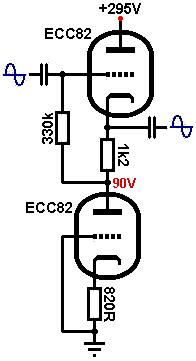
Using a triode as a constant current sink :
Suppose we wish to design a cathode follower with constant current sink. The HT is 295V and we decide to allow 90V across the CCS; this will be its quiescent anode voltage.
This leaves 295 - 90 = 205V across the cathode follower which is fairly low for most triodes. The ECC82 (12AU7) however, performs well at lower-than-average voltages.
We would like the cathode follower to be biased at exactly half HT for maximum headroom. Because we will force the current through the valve to be constant, we can simply draw a vertical line at a half HT and choose a bias point somewhere on it. We can then read off the constant current we need to obtain from the CCS.
In this case a half HT is half the voltage across the cathode follower only; 205 / 2 = 102.5V. We draw a vertical line corresponding to this (of course, you could choose a different voltage if you would like the cathode follower to clip sooner):
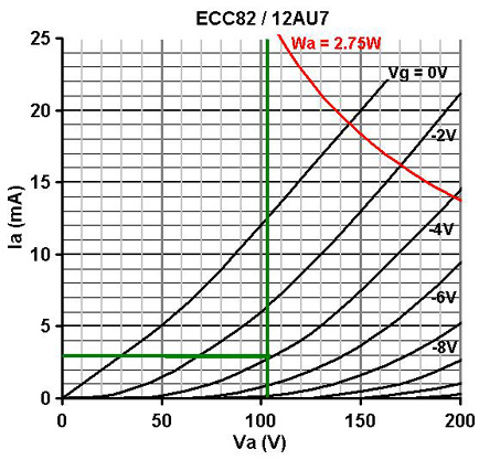
In this case the performance looks good at a bias voltage of -4V, giving an anode current of 3mA. This is the current we will need from the CCS.
We now need to select a valve that shows reasonable linearity at an anode voltage of 90V and anode current of 3mA. The ECC88 would be ideal but is rather expensive. The ECC81 and ECC83 would be operating in grid current territory. The ECC82 actually still operates well under these conditions so we can use that (which is convenient since there are two triodes in each envelope).
From the anode characteristics graph we can see that at Va = 90V, Ia = 3mA, the bias voltage is about -2.6V. Use Ohm's law to calculate the bias resistor for the CCS (Rk1):
2.6 / 0.003 = 867 ohms.
The nearest standard is 820R
We also chose the bias point of the cathode follower to be -4V. We know 3mA must flow, so use Uhm's law to calculate its bias resistor (Rk2):
4 / 0.003 = 1.3k
The nearest standard is 1.2k, and normal rules apply for the grid-leak resistor (Rg2).
(Of course, if the cathode follower is to be DC coupled then no bias resistor or grid leak is necessary. The grid can simply be set at four volts below the cathode which we have set to be 90V.)
The CCS now forms the load for the cathode follower instead of a resistor. The value of this load (at AC only) is:
r(ccs) = ra + (mu +1) * Rk
(ra is found from the anode characteristics graph at the bias point of the CCS (Va = 90V, Ia = 3mA). in this case it is roughly 20k)
r(css) = 20000 + (19 + 1) * 820
= 36.4k.
This is about twice as high as the value we would normally have used for the load on the cathode follower (see the section on the cathode follower for more theory), so its performance has been improved slightly but not impressively. We could have used a larger value for Rk1 to increase r(ccs), and set the grid bias on the CCS with a potential divider. You may also like to note that the circuit is very much like an SRPP, but we are feeding the upper grid rather than the lower.
A higher mu / higher ra triode would also have made a better CCS, and a pentode has a very high ra and would make an excellent CCS, giving values of r(ccs) typically in the order of several Meg-ohms! However, since the performance of a cathode follower is excellent anyway, the use of a CCS is more novelty than necessity. The performance of the long tailed pair on the other hand, can be improved massively with the use of a CCS tail.
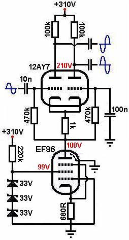
Using a pentode as a constant current sink :
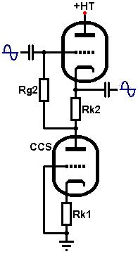
In the diagram [below] 100V has been allowed across the pentode CCS and it is set to pass 2mA of constant current. Exactly the same design process applies to using a pentode as a CCS as for the triode previously, except that you must also choose and set the screen voltage. See the section on the small signal pentode for this. The load seen by the pentode CCS is very low; formed by the cathode resistor and cathode impedance of the 12AY7. The screen voltage can therefore be made the same as the anode voltage quite safely.
Additionally, because the load on the pentode is so low, we needn't worry about noise from the pentode or zeners being amplified significantly.
The ra of the pentode is so high compared to its cathode resistor that r(ccs) can be approximated as being equal to ra. In this case it is roughly 2Meg, so this circuit has the effect of using a 2Meg tail resistor on the long tailed pair, without the drawbacks! The performance of the long tailed pair becomes so perfect that its anode resistors can be made equal and excellent balance is ensured (see the sections on the long tailed pair for the rest of the circuit).
Transistor constant current sink :
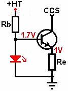
There are many possible CCS circuits using transistors, many of which become quite extensive. The one provided here is the simplest, requiring one NPN transistor and a minimum of components.
The red LED sets the base voltage at about 1.6V so the transistor is always 'on'. Rb is simply the current limiting resistor for the LED. Since it has to drop most of the HT at a few milliamps, it will usually need to be rated at 2W or more, unless there is a convenient, small positive supply voltage available. Alternatively, the base voltage could be acquired from the cathode of an LED biased gain stage.
The base-emitter drop is about 0.6V, therefore the voltage across the emitter resistor (Re) must be at 1.6 - 0.6 = 1V. The emitter resistor sets the current since there must be 1V across it, use Ohm's law to find its value.
For a constant current of 1mA :
1 / 0.001 = 1k
Note, this circuit may not work if Re is less than about 400 ohms because Vbe increases with current. If you need to sink more than about 2mA it is better to raise the base voltage by using an LED with a higher forward voltage, or zener diode.
The AC impedance obtained will be roughly equal to:
r(ccs) = Re * (2 * hfe) + 1 / hoe
Where:
Re = the emitter resistor
hfe = rated current gain (the "2" comes from the fact that hfe tends to be about double its normal value when Ibe is less than about 10mA)
hoe = ac impedance of the transistor
But hoe is typically very small indeed, then to a close approximation;
r(ccs) = Re * (2 * hfe)
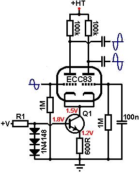
The diagram below illustrates how this CCS might be employed in the tail of a long tailed pair. Q1 may be any transistor, the higher the gain the better (the author used a ZTX615 with an hfe=170), and R1 should be sized to supply a couple of milliamps to the diodes. This particular circuit was tested and gave output signals that were less than 5% unbalanced, since it is equivalent to using an ordinary tail resistor of well over 100k!
If used with a cathode follower, large signal voltages will be developed across the transistor so it will need to have a high Vce(max) rating, unless most of the load resistance is placed abode the transistor. Possible options are the MPSA42 (0.6W) useful for constant currents less than about 2mA, and the MJE340 (20W) that can handle just about anything. Both are rated at Vce(max) = 300V.
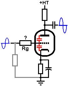
A resistor is often placed in series with the signal before it reaches the grid of a valve. This is known as a 'grid-stopper' and serves several purposes.
It is usual place the grid-leak resistor before the grid-stopper. This will increase the total grid-leak resistance so be sure not to exceed the maximum rated value. Adding it after the grid-stopper will create a potential divider that will attenuate the input signal slightly, which is usually avoided, although may be necessary in some cases.
Frequency response and the Miller effect :
Grid-stoppers can be used to control the high frequency roll-off response of amplfier stages.
On the input of an amp its function is to 'stop' radio frequencies (all those above 20kHz) from reaching the grid and causing unwanted interference. While this wouldn't damage the circuit, inaudible RF interference can damage tweeters, and you certainly don't want to hear your local radio station playing through your amp!
Wherever possible, the grid stopper should be soldered very close to, or directly onto the valve socket to maximise its effect, so that radio interference is less likely to be picked up on the wire between grid-stopper and valve grid.
The grid-stopper attenuates the RF by forming a low-pass RC filter with the valve's 'dynamic input capacitance'. This is the combination of the valve's static inter-electrode capacitances, plus the Miller capacitance.
The static inter-electrode capacitance is the product of all the internal capacitances within the valve, formed between the various metal parts. Miller capacitance is an effect produced within the valve (the Miller effect), such that the static grid-to-anode capacitance is actually multiplied by the gain of the stage. The static inter-electrode capacitances (those actually measured between valve pins), are quoted on the valve's data sheet, and the two most important are the grid-to-cathode (Cgk) and grid-to-anode capacitances (Cga), shown in red.
(Cgk may not be quoted, in which case the "grid to all except anode" capacitance should be used instead.)
The dynamic input capacitance (Cdyn) which you need to know when choosing a value for the grid stopper is:
Cdyn = Cgk + (Cga * A)
(Where: A = the voltage gain of the stage)
Using a typical ECC83 triode with a bypassed cathode as an example:
Cgk=1.6pF
Cga=1.6pF
A=60
Cdyn = 1.6 + (1.6 * 60)
= 97.6pF
The actual wiring within the amplifier will also have 'stray' capacitance, so it is usual to add a few extra pico-Farads to our answer to allow for this, making about 100pF in total.
To find a suitable value for the grid-stopper, simply apply the formula for a low-pass filter, where C is the dynamic input capacitance and f is the desired low roll-off frequency- in this case 20kHz:
Rg = 1 / (2 * pi * f * C)
Rg = 1 / (2 * pi * 20000 * (100 * 10-12))
= 79.6k
You will often see old amplifier designs using a 68k grid stopper. This will provide a roll-off of approximately 23kHz, which is close enough. However, the guitar itself also contributes a series resistance, that may range from a few kilo-ohms to several hundred kilo-ohms if the volume controls are turned down. This can easily cause treble frequenices to be rolled off, losing some of the high harmonics and 'chime' of the guitar sound. In practice it seems that in most cases the grid stopper can actually be made quite a bit smaller than 68k, and 10k to 33k will do, unless you happen to be playing nextdoor to a radio transmitter.
It is worth noting that in pentodes Cag is very small, so the dynamic input capacitance can be assumed to be roughly equal to Cgk.
Increasing Miller capacitance :
A further problem with the usual approach is that it places a very large value resistor in the signal path, which introduces noise. This isn't a worry in later parts of the preamp, but at the input we want to keep it to the bare minimum.
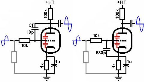
The grid stopper can be made smaller in value if the effective value of the input capacitance is made proportionately larger. This can be done by placing a capacitor between the anode and grid of the valve. This capacitor applies negative feedback of very high frequencies to the grid, and appears in parallel with the Miller capacitance, so its value is also multiplied by the gain of the stage, due to the Miller effect. Therefore the effective input capacitance is greatly increased and becomes equal to:
Cin = Cgk + (Cga * A) + (Cf * A)
Or: Cin = Cdyn + (Cf * A)
To use the previous example, a roll-off of 20kHz is desired, but this time with a grid-stopper of just 10k. The necessary effective input capacitance required would be:
Cin = 1 / (2 * pi * 20000 * 10000)
= 796pF
The value of the feedback capacitor would therefore be:
Cf = (Cin - Cdyn) / A
(where Cdyn is 100pF found earlier)
= (796 - 100) / 60
=11.6pF
In this case the closest standard value would be 10pF, providing an acceptable roll-off of about 23kHz. The capacitor used should be of high quality so as not to introduce its own noise, and should have sufficient voltage tolerance to withstand the anode voltage. A close tolerance ceramic capacitor would suffice.
For those afraid of the capacitor failing and placing a high voltage on your guitar strings, the capacitor could be placed between grid and cathode instead, although it will need to be a higher value since it won't be subject to the Miller effect. In this case:
796 - 100 = 696pF
The closest standard would be 680pF.
The succeeding gain stages in an amplifier are normally enclosed within an earthed chassis where RF interference is unlikely to be picked up, therefore RF blocking is usually only used on the input where the guitar and guitar lead can act as antennae. However, if RF is getting into an amp somewhere, it may be necessary to add a grid stopper and/or feedback capacitor to the offending valve.
Of course, we don't just have to limit RF. Any roll-off frequency can be chosen for this method, and it is often used to limit treble frequencies in bright amplifiers, and this is why you may see grid-stoppers in later stages within an amplifier.
Other reasons for grid-stoppers :
While the input of the amplifier will usually have a grid-stopper to remove radio interference, other stages in the amp- particularly the power valves- will often have grid-stoppers for different reasons.
The first is that the actual wiring inside the amp will have stray inductances. In combination with the input capacitance of a valve, this will produce a resonant circuit which can cause parasitic oscillation, particularly in high gm valves like power valves. This is cured by damping the resonance with a grid-stopper, fitted directly to the valve socket if possible. Data sheets will usually list a recommended value of grid-stopper, and typical values are around 1k to 10k on power valves. If in doubt, make it bigger. Most small signal valves don't suffer from this condition, although the ECC88 is an example of one that does.
The second reason is to limit grid current. In hifi this isn't such an important issue, but in a guitar amp the valves will often be driven well into grid-current territory. If left unchecked, this can cause the grid to exceed its ratings and be destroyed, although this is very rare.
The second reason is to limit grid current. In hifi this isn't such an important issue, but in a guitar amp the valves will often be driven well into grid-current territory. If left unchecked, this can cause the grid to exceed its ratings and be destroyed, although this is very rare.
The main reason for limiting grid-current is to reduce blocking distortion. By adding a grid-stopper, the input impedance of the stage cannot fall below the value of the grid-stopper. The maximum current that can flow in the grid is therefore limited, and the preceding stage cannot become so heavily loaded. By limiting the current we prevent the coupling capacitor from becoming fully charged during an overload, and therefore it can discharge faster once the overload has passed. Additionally, when current does start to flow during overload, the voltage drop across the grid-stopper will increase and so reduce the voltage on the grid countering, providing a voltage limiting effect as well as a current limiting one.
For a good, modern design, all valves should have grid stoppers, even if it a small value of around 10k say. Values up to 1Meg are quite reasonable though, and are a powerful tool in tweaking the overdrive and treble characteristics of the amp. Except for the input stage, the stopper does not need to be connected directly to the valve socket. Stages enclosed within a feedback loop (usually the output stage) are even more suseptible to blocking distortion so using large grid-stoppers will be even more necessary for these.
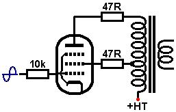
Screen-grid stoppers :
The screen-grid on a power pentode should also have a grid-stopper to protect it from over dissipation when the valve is overdriven, which causes the screen-grid to draw more current. The voltage drop across the screen-stopper will reduce the screen voltage, hopefully saving the valve from destruction. The resistor is usually 1k in value and at least 1W, although higher wattages are more preferable.
On ultra-linear power stages a grid-stopper on the screen-grid is not absolutely necessary, although for peace of mind it can be fitted. In hifi a 47R resistor is often used for this as it supposedly reduces distortion, and you sometimes see a similar resistor placed at the anode (anode-stopper) to quell parasitic oscillation or reduce distortion.
 Tweet
Tweet


Comment