Announcement

Collapse
No announcement yet.

โมให้ดีกันเยอะแล้ว มาม๊ะ....มาโมให้"เจ๊ง"กันดีกว่า

Collapse
X
 
  • Filter
  • Time
  • Show
Clear All
new posts

  • ------พักโปรเจ็คdac ชั่วคราว-----
    รื้อ PSU มาดูเล่น ตอนตัดที่รัดสายไฟ เผลอ ไปตัดโดนสายไฟพัดลม ซ่อมก่อน
    ค่อยว่ากันต่อ

    แต่แอบรู้ความลับ PSU มาหลายอย่าง

    -ใช้ c แบบ ceremic หรือ tatalum ไม่รู้ ตัวสีฟ้าๆเยอะมาก ไม่มีอะไรกำกับอ่านค่าไม่ได้

    -กาวยางเยอะมาก เข้าใจแล้วว่าใส่ทำไม เพราะ จัดวงจรมาอย่างงั้น อุปกรณ์บางตัว
    ตัวถังมันอาจจะชนกันทำให้ช็อตได้ เลย ต้องเอากาวยางกัน
    แต่ใส่ไม่ค่อยดี ไปเลอะจุดไม่เกี่ยวข้องด้วย

    -พัดลมขาด PSuมันก็ทำงานได้ แต่ต้องopen air หน่อย เดี๊ยวร้อนดับ

    -PSU รุ่นที่ใช้ 12vแบ่งจ่าย4เฟส แต่ไม่ได้บอกว่าเฟส ไหน คือแจ็คตัวไหนบ้าง
    สงสัยมานานแหล่ะ เวลาฮาร์ดดิส โหลดที่ไหล กระตุกทุกที

    เพราะ เฟส s-ata มันใช้ร่วมกัน กับ 12v4pinต่อเข้าเมนบอร์ด
    แถมยังร่วมกับ เฟส จ่ายไฟ12v8pin ที่จ่ายให้ กราฟฟิคการ์ดอีก

    12v เฟส1 สายใหญ่ลงบอร์ด
    12v เฟส... ไม่เห็นเลข จ่าย ลง4pin ที่cpu จ่าย sata อีก4หัว จ่าย12v8pin ของกราฟิคการ์ด
    12v เฟส... จ่ายไป4pin molex 4หัว <<(ทำ ทำไม= =" เอาใจคนใช้ide เหรอ
    หรือว่าเอาใจ คนชอบติดพัดลม molex4pinเยอะๆ )
    12v เพส4 จ่ายไป 12v6 pin 2หัว

    12 v 18a ต่อเฟส

    - อยากจะwire สายไฟใหม่มาก แต่ถ้าจะโล๊ะยากมากพอกตะกั่วไปซะเยอะเลย
    สายไฟแน่นมาก จนถอดบอร์ดออกจากตัวถังไม่ได้ติดสายไฟ
    = =" จะโมc คง
    ต้องถอดสายไฟออกให้หมด งานหนักเลย


    เหลือข้อดีตรงที่ตอนที่ไม่โหลดกระทันหัน จะจ่ายไฟนิ่ง ได้80+ วัตต์เยอะ แต่ถ้าจะไม่เต็ม
    (เพราะบอกmax ไม่ได้บอกcontinuos ยี่ห้อเทพๆ จะบอกcontinuos)

    Comment


    • Originally posted by keang View Post
      -- ใครเข้ามาอ่าน แล้วเอาไปโม แต่ไม่มาเล่าประสบการณ์ให้เพื่อนฟัง ผมถือว่าไม่แฟร์ --
      -- ฉะนั้น ใครเอาไปโม ผลลัพท์จะดีหรือไม่ดี ควรกลับมาเล่าประสบการณ์แบ่งปันให้เพื่อนๆรับรู้ด้วย --
      ผมตามมาอ่านเฉยๆ นะพี่ เรื่องโมนี่ ไม่กล้าจริงๆครับ เพราะปาดเหงื่อไม่ทัน จ่ายไปหลาย - -'

      Comment


      • Originally posted by keang View Post

        -- สงสัยมานานละ เห็นใช้DACต่อUSBกัน ทำไมไม่ทำสายUSBดีๆใช้กัน บ้านหม้อรู้สึกจะมีหัวขายครบเลยน่ะ --
        -- ส่งรหัสลับให้คนทำสายขายได้ยิน ::: คนทำสายสัญญาณขาย ไม่ลองทำสายUSBดีๆมาขายบ้างละ --
        สาย USB ผมใช้เจ้านี่อยู่


        เสียงและรายละเอียดชิ้นดนตรีต่างกันเยอะกับของเดิม ใครว่าส่งดิจิตอล 10100 เหมือนกันแล้วไม่มีผล

        Comment


        • Originally posted by ManiacMaew
          - ใช้ c แบบ ceremic หรือ tatalum ไม่รู้ ตัวสีฟ้าๆเยอะมาก ไม่มีอะไรกำกับอ่านค่าไม่ได้
          ไม่ใช่แบบที่คิดครับ เป็นตัวเก็บประจุสำหรับไฟAC ป้องกันพวกSURGE พวกTRANSIENT
          จะพบมากในระบบที่การป้องไฟกระชากแบบฉับพลัน หรือ พวกAC Line Filter

          ลองดูกระทู้นี้ แนะนำตัวกรองไฟ งบไม่เกินซัก 3-4 พันหน่อยครับ

          Originally posted by TuiLor
          ผมตามมาอ่านเฉยๆ นะพี่ เรื่องโมนี่ ไม่กล้าจริงๆครับ เพราะปาดเหงื่อไม่ทัน จ่ายไปหลาย
          มีเวลาลองเปรียบเทียบเสียงของ "Titanium HD" เทียบกับ "ELITE PRO" ให้ฟังหน่อย
          ( เทียบแบบต่อตรงกับการ์ดELITE ไม่ใช่ต่อแบบผ่านConsole Boxน่ะ )
          ไม่ต้องสนใจว่าใครจะชอบใครไม่ชอบ เรื่องของเรื่องคือจะให้เล่าให้ได้ว่างั้นเหอะ

          เอาน่า ได้ของดีมาใช้ ไม่ใช่ไปทำเงินหล่นหาย

          Originally posted by lucifur
          ใครว่าส่งดิจิตอล 10100 เหมือนกันแล้วไม่มีผล
          นี่ละครับ คือ สิ่งที่ผมต้องการสื่อ
          Last edited by keang; 11 Aug 2010, 11:58:45.

          Comment


          • Resistor Construction

            เครดิตเวป Learnabout-Electronics

            Resistor Construction

            Fixed Resistors
            Resistors are components having a stated value of RESISTANCE. Many types of resistors are used having different uses and construction. The most common types have a fixed value of resistance so are often called fixed resistors. They are shown on circuit schematic diagrams (theoretical diagrams that show how the circuit components are connected electrically, rather than what a circuit looks like physically) using one of the following symbols.


            Various types of fixed resistors are used in circuits, they are the most numerous of all electronic components and their most common job is to reduce voltages and currents around a circuit so that "active components", transistors and integrated circuits for example, that carry out tasks such as producing or amplifying signals within the circuit are supplied with the correct voltages and currents to work properly.

            Resistors are also used in conjunction with other components such as inductors and capacitors to process signals in many ways.

            Because resistors are "passive components" they cannot amplify or increase voltages currents or signals; they can only reduce them. nevertheless they are a most essential part of any electronic circuit.


            1. SMT (Surface Mount Technology)
            Many modern circuits use tiny SMT resistors. These are made by depositing a film of resistive material such as tin oxide on a tiny ceramic chip. The edges of the resistor are then accurately ground, or cut with a laser to give a precise resistance across the ends of the device. Tolerances may be as low as 0.02%. Contacts at each end are provided, which are soldered directly onto the conductive print on the circuit board, usually by automatic assembly methods. Although they normally have only very low power dissipation, very high component density can be achieved.

            2. Carbon Film Resitor
            Similar construction to Metal film resistors but generally with wider tolerance (typically +/- 5%) Shown here mounted on paper strips for machine insertion into printed circuit boards. Small resistors are extremely inexpensive components and are also often sold in batches of 10s or 100s in this form for easier handling.

            3. Carbon Composition Resistor

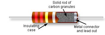
            Carbon composition are the oldest design and usually the cheapest of the resistors. Carbon granules are mixed with a filler material and inserted into a tubular casing. In earlier types vulcanised rubber was used but in modern designs the carbon is mixed with a ceramic filler. The value of resistance is determined by the amount of carbon added to the filler mixture. Carbon composition resistors do not have the close tolerances of either carbon or metal film types. Typical tolerances are +/-10% or 20%. One advantage however is that they are better suited to applications involving large voltage pulses than the more modern types.

            4. 1 Watt resistor
            Carbon composition, carbon and metal film resistors are available in a range of power ratings. In a resistor, the power that the resistor must dissipate (get rid of as heat) depends on the voltage difference (V) across the resistor and the current (I) flowing through it. These are multiplied together to obtain the amount of power (P) that must be dissipated using the formula P = IV. For any particular type or value of resistor, the greater the power rating, the larger the physical size of the resistor.

            5. Wire-wound resistor

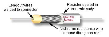
            Wirewound resistors are very variable in construction and physical appearance. Their resistive elements are commonly lengths of wire, usually an alloy such as Nickel/Chromium (Nichrome) or Manganin (Copper/Nickel/Manganese) wrapped around a small ceramic or glass fibre rod and coated in an insulating flameproof cement film. They are normally available in quite low values of resistance (single ohms to a few Kilohms) but can dissipate large amounts of power. In use they may get very hot.

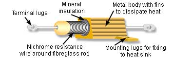
            For this reason high power wirewound resistors may be housed in a finned metal case that can be bolted to a metal chassis to dissipate the heat generated as effectively as possible. With all types of wirewound resistor, fire protection is important and flame proof cases or coatings are vital. Lead-out wires are normally welded rather than soldered to the resistor.

            6. Metal film resistor

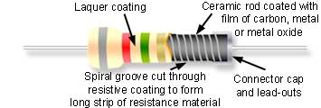
            These resistors are made from small rods of ceramic coated with metal (such as a nickel alloy) or a metal oxide (such as tin oxide). The value of resistance is controlled firstly by the thickness of the coating layer (the thicker the layer, the lower the value of resistance). Also by fine spiral groove cut along the rod using a laser or diamond cutter to cut the carbon or metal coating effectively into a long (spiral) strip, which forms the resistor. Metal film resistors can be obtained in a wide range of resistance values from a few Ohms to tens of millions of Ohms with a very small TOLERANCE. For example a typical value might be 100KΩ +/- 1% or less i.e. for a stated value of 100KΩ the actual value will be between 99KΩ and 101KΩ. Note that although the body colour on metal film resistors is often grey, this is not a reliable guide. Small carbon, metal and oxide resitors may be made in various body colours such as dark red, brown blue green grey or white.

            7. 5 Watt Wirewound Resistor
            A wirewound resistor can have a smaller physical size for a given power rating than carbon composition or film resistors; compare this 5W resistor with the 1W resistor at 3. Wirewound resistors however, do not not have the close tolerance of composition or film types. This 4R7 resistor has a tolerance of 10%

            8. PCB Mounting Wirewound Resistor
            Wirewound resistors usually have a resistance range from around 1Ω to about 50KΩ. Because they use a coil of wire as their resistive element they tend to act as inductors to some degree. This limits their use to low frequency circuits up to around a few tens of kiloHertz. This example, available in power ratings up to 25W, is for mounting on a printed circuit board and to prevent heat damage to the board, the specially shaped legs ensure an air gap between the resistor and the board; the whole resistor is enclosed in a flameproof ceramic case.

            9. High Power Metal Film
            Metal film resistors are also available in high power types with power ratings less than wirewound types (typically less than 5W) but having closer tolerances.

            10. Fusible Wirewound Resistor
            In this fusible resistor, the current flowing through the resistor first flows through a spring loaded connection that is positioned close to the body of the resistor. The heat generated by the wirewound resistor under normal conditions would not be sufficient to to melt the blob of solder holding a spring wire in place. If too much current flows through the resistor it overheats, the solder melts and the wire springs up, opening the connection and stopping the current. This then requires a service technician to find the cause of the overcurrent before resoldering the spring connection to restore normal operation. It is important to use the correct type of solder when resoldering, since this will affect the temperature at which the spring opens.

            Comment


            • Resistor Color Code

              เครดิตเวป Learnabout-Electronics

              Resistor Color Code

              4 Band Color code


              5 Band Color code


              6 Band Color code

              Comment


              • Originally posted by keang View Post
                มีเวลาลองเปรียบเทียบเสียงของ "Titanium HD" เทียบกับ "ELITE PRO" ให้ฟังหน่อย
                ( เทียบแบบต่อตรงกับการ์ดELITE ไม่ใช่ต่อแบบผ่านConsole Boxน่ะ )
                ไม่ต้องสนใจว่าใครจะชอบใครไม่ชอบ เรื่องของเรื่องคือจะให้เล่าให้ได้ว่างั้นเหอะ

                เอาน่า ได้ของดีมาใช้ ไม่ใช่ไปทำเงินหล่นหาย
                อะนะพี่ ตอนนี้ได้แต่ฟังผ่านๆ หน่ะครับ รอของที่พี่สั่งมา จะเอาการ์ดแวะไปให้พี่ พร้อม Console ให้พี่โมแล้วมานั่งเทียบ อิอิ

                Comment


                • ซ่อม PSU เสร็จแล้ว
                  พบวิธีปรับปรุงแบบง่ายโคตรๆ

                  คือ อย่าไปเสียบอุปกรณ์หลายอย่างเฟสเดียวกัน
                  แต่ถ้าไม่แกะมาดูคงไม่รู้ว่าหัวไหนเฟสไฟน

                  แต่ไฟเลี้ยง CPU กับ sata ดันเฟสเดียวกัน
                  หัว molex 4pin ที่คนละเฟสกันก็ดันเป็นตัวผู้ เอาสายไฟideแปลงเป็นsataปกติ มาใช้ไม่ได้
                  เพราะหัวมันจะตัวผู้เหมือนกัน
                  จะแปลงหัวเองแหล่ะ แต่ดันทำอย่างอื่นตะกั่วหมดเลยอดทำไป

                  เหลือบ ไปเห็นที่เมนบอร์ดอีกจุด สามารถเซ็ตจัมเปอร์
                  ไฟ USB1-4 กับ 5-8 ได้ ว่าจะเอามาจาก 5V หรือ5Vsb
                  ตอนนี้เลยเซ็ท ส่วนฟรอนท์ (5-8) ไป5Vsb ให้พลังงานน้อยกว่า แต่ต่อแค่จอยสติกซ์
                  จะไม่ได้ไม่แย่งไฟเลี้ยงdac เพราะ ตัวชิพrevier ใช้ไฟจาก usb

                  ลองดูเมนบอร์ดของตัวเองกันบ้างน่ะครับ บ้างทีอาจจะมีวิธีง่ายๆ แต่ทำให้ได้อย่างที่เหมาะสมขึ้น
                  (ขอใช้คำว่าเหมาะสมน่ะครับ เพราะ set jumper แต่ล่ะส่วนมันมีเหตุผลของมัน การใช้งานไม่เหมือนกัน)
                  = =" ยิ่งรุ่นคุณปู่ นี้ ทุกอย่างมันเซ็ทจัมเปอร์หมด


                  เรื่องสาย USB คงไว้ก่อน ตอนนี้ มันมาอั้น ที่ rca to mini female ซะมากกว่า
                  หาแบบดีไม่ได้สักที ไปบ้านหม้อ มา3-4รอบแล้ว= ="

                  ดูที่หน้าแรก จะมีบอก ปีไว้ครับ ลองดูว่าปีไร จะได้เทียบกับที่ผมมีอยู่
                  ค่าไม่ตรงกันแบบนี้ แสดงว่ามีการปรับปรุงค่าใหม่ เพื่อให้การทำงานดีขึ้น
                  Pcm 2706 datasheet rev. june 2009


                  "คนอ่านแต่ไม่ได้ทำ ก็เหมือนคนมีแผนที่ แต่ไม่ได้เดินทาง
                  คนทำแต่ไม่ได้อ่านเลย ก็เหมือนคนเดินทาง แบบไม่มีแผนที่"
                  เอามาจากไหนไม่รู้ลืม

                  Comment


                  • วงจรพื้นฐาน ไอซีเรกกูเลเตอร์ 78xx 79XX

                    วงจรพื้นฐาน ไอซีเรกกูเลเตอร์ 78xx ( ไฟบวก + )


                    วงจรพื้นฐาน ไอซีเรกกูเลเตอร์ 79xx ( ไฟลบ - )


                    ลองอ่านคำอธิบายใต้รูป เพื่อเข้าใจถึงการใช้ตัวเก็บประจุ
                    - จุดไหนสำคัญต่อการทำงานของวงจร
                    - จุดไหนจำเป้นต้องมี จุดไหนไม่จำเป็นต้องมี
                    - ถ้าจะใช้ ควรใช้ค่ามากน้อยแค่ไหน


                    ------------------------------------------


                    Originally posted by ManiacMaew
                    Pcm 2706 datasheet rev. june 2009
                    PCM2706 : SLES081A − JUNE 2003 – REVISED MAY 2004
                    PCM1793 : SLES076A − MARCH 2003 − REVISED JANUARY 2004
                    Last edited by keang; 12 Aug 2010, 13:52:31.

                    Comment


                    • มาโม Amp เล่นกันดีกว่าครับ - หน้า 4
                      เห็นกระทู้โมแอมป์ของคุณmilestone มีคนเปลี่ยนฝาครอบด้านบนเป็นอะครีลิค DAC Z2ก็เป็นอะครีลิคเหมือนกัน

                      เอาเรื่องสนุกมาฝาก ให้ได้ลองสังเกตุกันเล่นๆดีกว่า


                      ฝาครอบ หน้าที่หลักคงเป็นเรื่อง เพิ่มความแข็งแรงของโครงสร้าง และ ชีลด์
                      ( ป้องกันสนามแม่เหล็กสนามไฟฟ้าจากภายในออกสู่ภายนอก และจากภายนอกเข้าสู่ภายใน )
                      ป้องกันฝุ่นหรือความสวยงามเป็นของแถม

                      ฝาครอบด้านบนของตัวเครื่อง ส่วนใหญ่จะใช้วัสดุ เหล็ก, เหล็กชุบทองแดง, อลูมิเนียม, ทองแดง
                      ปัจจุบันซาวน์การ์ดก็เล่นกับเค้าด้วย ส่วนใหญ่จะเป็นอลูมิเนียม

                      เจ้าของเครื่องก็มีการเติมแต่งความสวยงาม เช่น เปลี่ยนจากโลหะเป็น ไม้, กระจก, อะครีลิค ฯลฯ
                      บางรายอาจใส่แสงสีเข้าไป ดูแปลกตากันไปตามรสนิยมของแต่ละคน


                      หลังจากเปลี่ยนฝาครอบไปแล้ว
                      เมื่อเปิดเครื่องใช้งานตามปรกติ เจ้าของเครื่องบางคนเกิดความรู้สึกสงสัยลังเลไม่แน่ใจ
                      เสียงมันไม่เหมือนเดิม บางอย่างมันต่างจากเดิม

                      สายไม่แน่น? เสียบสายไม่สนิท? เสียบผิดช่อง? สายลำโพงที่ลากไว้กับพื้นมีใครไปเตะโดนมั๊ย?

                      ไม่น่าใช่ เพราะไม่ได้ถอดสาย ไม่ได้รื้อเครื่องเพื่อเปลี่ยนอะหลั่ยหรืออุปกรณ์ จะมีก็แค่เปลี่ยนฝาครอบด้านบนเท่านั้นเอง
                      แต่เหตุใดเสียงต่างจากเดิม ทำไม ทำไม ???

                      กลับไปดูที่ตัวเครื่องเพื่อตรวจสอบทุกอย่างอีกครั้ง แต่ดูแล้วก็ปรกติเหมือนเดิมทุกอย่าง


                      หลักการแก้ปัญหาหรือข้อสงสัยเบื้องต้น "ปัญหาเกิดจากไหน ต้องแก้ที่จุดนั้น"
                      จัดการรื้อฝาครอบอันใหม่ออก ใส่ฝาครอบเดิมกลับคืนที่
                      ลองฟังใหม่อีกครั้ง คราวนี้เหมือนของเดิมแล้ว

                      ด้วยความที่ลงทุนกับฝาครอบใหม่ไปแล้ว ความอยากใช้ของใหม่ยังมีอยู่
                      เปลี่ยนใหม่อีกครั้ง คราวนี้บรรจงใส่ด้วยความปราณีตขึ้น

                      เฮ้ยยยย เสียงต่างอีกแล้ว เสียงไม่เหมือนเดิมอีกแล้ว
                      คราวนี้ตั้งใจสังเกตุแบบจับผิด พบว่า นอกจากเรื่องเสียงแล้ว มิติเวทีเสียงยังต่างจากตอนใส่ฝาครอบเดิมด้วย

                      เกิดไรขึ้น? ผีหลอก? ไสยศาสตร์? ???
                      ฝาครอบเครื่องมีผลกับเสียงด้วย ???
                      ตลกเกินไปแล้ว บ้าเกินไปแล้ว


                      หากต้องการทดลองผลของฝาครอบ คุณไม่จำเป็นต้องทำฝาครอบขึ้นมาใหม่
                      ลองง่ายๆเพียงแค่ "มีฝาครอบของเดิม" กับ "เปิดฝาครอบ(ไม่ใส่)"
                      ขอให้เครื่องคุณมีความสามารถในการให้รายละเอียดได้สูงหน่อย และ สามารถให้มิติเวทีเสียงได้บ้างก็พอ
                      - สังเกตุระดับความสูงของเสียง
                      - สังเกตุรายละเอียดและลักษณะของเสียงกลางกับแหลม
                      - สังเกตุลักษณะของเสียงทุ้ม


                      -- ลองช่วยกันหาเหตุผลหรือสมมุติฐานต่างๆ เหตุใดบ้างที่อาจส่งผลให้เกิดความแตกต่าง --
                      -- ขอให้ใช้สมมุติฐานหรือแนวคิดเป็นวิทยาศตร์ เพราะเหตุมันเกิดจริง มีผลจริง --
                      -- แนวคิดที่คิดว่าเป็นไสยศาสตร์หรือเล่นกล เอาไว้หลอกเด็กดีกว่า --

                      ผมเสริมให้นิดนึง ลองทำความเข้าใจเรื่องเหล่านี้
                      - วัสดุที่เห็นความต่างได้ง่าย เหล็กหรือทองแดง, อลูมิเนียม, อครีลิค, ไม้
                      - ลักษณะและรูปแบบของสนามแม่เหล็ก
                      - ลักษณะและรูปแบบของสนามไฟฟ้า
                      - ลักษณะพื้นผิวของวัสดุต่างๆ
                      - การซึบซับและการสะท้อนกลับของวัสดุต่างๆ
                      Last edited by keang; 12 Aug 2010, 13:49:47.

                      Comment


                      • คำถามข้างบน ขออนุญาติแตกกระทู้นะครับ เห็นแล้วน่าสนุก อิ อิ

                        Comment


                        • เออในความรู้สึกผม เสียงที่ได้ก่อนและหลัง เปลี่ยนฝา อคลิลิก ต่างกันแค่เสียงแหลมครับ(พวกกีต้า) นอกนั้นก็ปกติดี(ซ่าพอควร ยังไม่ได้เปลี่ยนไรเลยนอกจากสาย)

                          อันนี้เท่าที่ผมฟังออกน่ะครับ

                          ตามไปเสพโดยพลัน !!
                          แปะให้ของคุณ milestone
                          http://forums.overclockzone.com/foru...d.php?t=971865
                          Last edited by pluanant; 12 Aug 2010, 17:38:48.

                          Comment


                          • อ้างอิง:
                            ข้อความดั้งเดิมโดยคุณ ManiacMaew
                            ขากราวน์นี้เอาไปต่อลงไหนครับ ลงตัวเคสเหรอครับ
                            ถ้าแบบยึดติดpcb ขากราวน์ ก็ต่อลงpcb ใช่มั้ยครับ?

                            ไม่ควรต่อลงที่เคสครับ ควรต่อลงpcbที่จุดกราวน์ตำแหน่งเดิมของrca jack
                            ไม่น่าจะต่อแบบเดิมได้ครับ ว่าจะทำแผ่นยึด หัวมาตั้งฉากแล้วเอาหัวใหม่มาต่อ
                            แล้วต่อกราวน์ลงแผ่นยึดแทนได้มั้ย


                            อ้างอิง:
                            ข้อความดั้งเดิมโดยคุณ ManiacMaew
                            c feed back หาค่าเดิมไม่ได้นี้ จะใส่ค่าอื่นแทนได้มั้ย?

                            ในวงจรผู้ผลิตชิบใช้ค่าไร ตัวจริงใส่ค่าไร
                            ค่าเดียวกันกับในdatasheet เลยครับ 560pf
                            silver mica ที่น่าจะหาได้ คือ 500 510 หรือ 600 pf ไปเลย


                            review second mod.

                            Z2mod2.jpg
                            ถอด bicap wima0.1uf ตรงไฟเลี้ยงopampออก
                            +
                            DSC08469.JPG

                            เปลี่ยนadaptor จากswitching 12V 1A เป็น transformer 24V 1A


                            สะงัดขึ้นมากๆ เพิ่งมาเข้าใจคำว่าสะงัดก็ตอนนี้แหล่ะ ความขุ่นมัวลดลงเยอะมาก
                            เป็นผลมาจากadaptorน่ะครับ ลองเช็ค กับadaptorตัวเก่าแล้ว

                            มิติ
                            ด้านกว้าง ให้ความรู้สึกกว้างพอๆกับz2เดิมๆ
                            ด้านลึก มีมากกว่าMod1 พอๆกับZ2เดิมๆ
                            เสียงSurround ประเภทออกซ้าขวาเท่ากันแยกจากcenter ได้ง่ายขึ้น มันจะถอยไปข้างหลังหน่อยๆ
                            ด้านสูง มีมากขึ้นจากZ2เดิมๆ และ mod1
                            เหมือนจะทำได้ดีขึ้นนิดๆ เครื่องดนตรี ที่อยู่สูงเหมือนกัน แยก ระดับว่าสูงต่างกันได้บ้าง
                            เสียงร้องบางเพลง จากระดับสูงที่อยู่เหนือปลายจมูกนิดๆ ขึ้นมากลางหน้าผาก
                            ส่วนลงล่างยังไม่แน่ใจ

                            กว้าง*สูง ทำได้ขึ้นพอตัว
                            แยก focus จุดวางเครื่องดนตรี ได้ดีกว่าเดิมบ้าง
                            สมมุติว่า มี 2เครื่องดนตรีอยู่สูงเหมือนกัน อันที่สูงเยื้องซ้าย กับสูงเยื้องขวา
                            จะแยกได้ว่าระดับสูงต่างกัน บ้าง


                            ไม่ค่อยแน่ใจ เริ่ม ลืมเสียงเก่าๆ แต่ร่วมๆ แล้วมิติดีขึ้น

                            เบส กระชับเท่าMod1 แต่การพุ่ง มวลกับimpactลดลง แต่ยังมากกว่าZ2เดิมๆ
                            กลาง ไม่พุ่งไม่เด่นเท่าmod 1
                            แหลม ไม่หลบเท่าMod1
                            ให้รายละเอียดเสียงดีกว่าMod1 ไม่โดนพวกกลางหรือupper เบสกลบ

                            ร่วมๆ เบสกลางแหลม คล้ายๆ Z2 เดิมๆ แต่เบสกระชับกว่า กระพือกว่า
                            เสียงทุกช่วงห้วนกว่าหน่อย

                            สรุป
                            เทียบๆกับZ2เดิม
                            สะงัดกว่ามากๆ มิติ ดีขึ้น เบสกระชับขึ้น impactมากขึ้น
                            แต่เสียความหวานของเสียงนักร้องหญิงไปเล็กน้อย
                            แยกรายละเอียดชิ้นดนตรีได้ง่ายขึ้นอาจจะเป็น ผลพ่วงจากเรื่องมิติมั้ง เสียงมันไม่ซ่อนกัน

                            เสียงใกล้ได้จุดที่ต้องการแล้ว

                            หมายเหตุ เทสบนsystemเดิม
                            ข้อควรระวัง ให้กลับไปดูที่review Mod1
                            ข้อควรระวังเพิ่ม
                            ไม่ได้เบิร์น เพราะ โล๊ะของเก่าออกไม่ได้ใส่เพิ่ม เว้นadaptor ซึ่งไม่ได้มีผลเรื่องอื่นเท่าไร
                            นอกจากความสะงัด
                            +การสังเกตอาจจะเปลี่ยนไป เริ่มลืมเสียงเก่าแล้ว และก็ วิธีสังเกตจะเปลี่ยนจากตอนแรกหน่อยๆ
                            เนื่องจากประสบการณเปลี่ยนไป


                            จริงก็ไม่ได้ทำอะไรเยอะเลยทั้งหมดที่ทำมา
                            1เปลี่ยน c ไฟเลี้ยง opamp
                            2เอา bicap ออก
                            3เปลี่ยนadaptor
                            ที่มาไกลจริงๆ คือเรื่องอ่านลายวงจร

                            c nippon ยังหาค่า 10u/ 16-25v ไม่ได้เลย= =" ว่าจะลองเอามาเปลี่ยนตามdatasheetดู version ของผมใหม่กว่า
                            Last edited by ManiacMaew; 27 Aug 2010, 17:50:59.

                            Comment


                            • ลองใช้ batteries จ่ายไฟแทนหม้อแปลงครับ

                              Comment


                              • Originally posted by lucifur View Post
                                ลองใช้ batteries จ่ายไฟแทนหม้อแปลงครับ
                                เห็นด้วยจ้า น่าลองนะครับ

                                Comment

                                Working...
                                X