Announcement

Collapse
No announcement yet.

D.I.Y.ตอน ต่อแอมป์ 40+40 w. ราคาไม่ถึงพัน

Collapse
X
 
  • Filter
  • Time
  • Show
Clear All
new posts

  • อ่าวหรอ ผมก็คิดว่าเป็นเทคนิคอะไรซะอีก คือหาค่า ไม่ได้ว่างั้นเหอะ
    Originally posted by Wizardmans View Post
    เพื่อให้ได้ค่าความต้านทาน ที่ต้องการครับ

    Comment


    • Originally posted by fenderfree View Post
      อ่าวหรอ ผมก็คิดว่าเป็นเทคนิคอะไรซะอีก คือหาค่า ไม่ได้ว่างั้นเหอะ
      ค่าที่ต้องการมันไม่มีทางที่จะหาซื้อ ได้อยู่แล้วครับ

      Comment


      • ไม่ใช้พวก trim pot ล่ะครับ หรือมันสิ้นเปลืองไป

        Comment


        • Originally posted by fenderfree View Post
          ไม่ใช้พวก trim pot ล่ะครับ หรือมันสิ้นเปลืองไป
          fix ค่านี่แหละครับ ดีที่สุดแล้ว

          Comment


          • ก่อน

            หลัง

            ---------------------
            C เบอร์ไหนมันอยู่ตรงไหนบ้างเนี่ย ลืมจดอ่ะ = ='

            ใครพอรู้บ้างครับ

            Comment


            • กรรม ดูจากรูปแล้วเดาขนาดไซส์เอาครับ ไม่งั้นต้องขอให้คนมีเขารื้อให้ดู

              วันหลังจด ไม่ก็ทำทีเป็นช่วงๆ ครับ โล๊ะทีเดียวหมดแบบนี้ มีมึนถ้าไม่จด

              Comment


              • pcbกับเลย์เอ้าท์คุ้นๆ เหมือนมีคนเพิ่งโมไปไม่นาน ลองค้นกระทู้แล้วเทียบค่ากับในรูปครับ

                Comment


                • Originally posted by ManiacMaew View Post
                  กรรม ดูจากรูปแล้วเดาขนาดไซส์เอาครับ ไม่งั้นต้องขอให้คนมีเขารื้อให้ดู

                  วันหลังจด ไม่ก็ทำทีเป็นช่วงๆ ครับ โล๊ะทีเดียวหมดแบบนี้ มีมึนถ้าไม่จด
                  นั่นสิครับ ผมลืมข้อนี้ไปเลย ดันมาจดเบอร์ตอนถอดเสร็จอย่างเดียว

                  Originally posted by keang View Post
                  pcbกับเลย์เอ้าท์คุ้นๆ เหมือนมีคนเพิ่งโมไปไม่นาน ลองค้นกระทู้แล้วเทียบค่ากับในรูปครับ
                  อ๊ะ เห็นแล้วครับ http://www.overclockzone.com/forums/...8D%8D%E5%8D%8D

                  ผมก็เคยเข้าไปชมเหมือนกันนี่หน่า

                  Comment


                  • กระทู้นั้น เค้าเอาไว้รีวิวหลังจากเปลี่ยนอะหลั่ยแล้ว
                    รายละเอียดการโมอยู่ในกระทู้นี้แหล่ะครับ หน้า15 คลิก
                    ลองไล่อ่านดู จะมีบางหน้าบางโพสที่เป็นรูปใหญ่เห็นค่าอะหลั่ยชัดหน่อย

                    Comment


                    • ลืมบอก จริงๆ อยากให้ค่อยๆทำทีละจุดหรือ2จุดถ้าเกิดมันพลาด หรือ เสียงไม่ได้อย่างต้องการจะได้หาจุดได้ง่าย
                      ต่อไป จะจำเสียงอะไหล่บางส่วนได้ ทำครั้งต่อๆ มันจะง่าย

                      Comment


                      • รบกวนถามหน่อยนะครับ แบบนี้ค่าความผิดพลาดจะกลายเป็น 15% หรือเปล่าท่านพ่อมด
                        Originally posted by Wizardmans View Post


                        2SK1058+2SJ162

                        Comment


                        • Originally posted by fenderfree View Post
                          รบกวนถามหน่อยนะครับ แบบนี้ค่าความผิดพลาดจะกลายเป็น 15% หรือเปล่าท่านพ่อมด
                          ไม่หรอกครับ ผมวัดก่อนทุกตัว ก่อนลงอุปกรณ์ครับ ที่ไม่ใช้ royal 1% เพราะเสียงมันดุไปหน่อย

                          Comment


                          • Originally posted by fenderfree
                            รบกวนถามหน่อยนะครับ แบบนี้ค่าความผิดพลาดจะกลายเป็น 15% หรือเปล่าท่านพ่อมด
                            ค่าผิดพลาดรวม = ค่าผิดพลาดของตัวRที่เอามาใช้ครับ
                            ( ใช้Rค่าผิดพลาด5% จะต่ออนุกรมหรือขนานกี่ตัว ค่าผิดพลาดก็ยังเป็น5%เหมือนเดิม)
                            ต่อแบบอนุกรมหรือขนาน ไม่มีผลเรื่องค่าผิดพลาดรวม

                            Comment


                            • Originally posted by keang View Post
                              เห็นหลายคนบ่นเรื่องใช้ไมค์กับซาวน์การ์ดแล้วเสียงเบา สู้ต่อผ่านมิกเซอร์ไม่ได้เพราะเสียงดังกว่า
                              จริงๆมันก็ไม่แปลก เพราะซาวน์การ์ดมีวงจรขยายแค่ขั้นเดียว แต่พวกมิกเซอร์มันมีวงจรปรีไมค์ในตัว

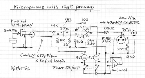
                              เสริชเวปนอกเจอวงจรปรีไมค์ ดูแล้วน่าสนใจ ลงทุนก็ไม่เท่าไหร่ เผื่อจะมีคนสนใจลองทำใช้กัน

                              Panasonic WM61A Omnidirectional Back Electret Condenser Microphone Cartridge
                              ดาต้าชีท

                              รูปโครงสร้างวงจรภายในของไมค์คอนเดนเซอร์


                              รูปไมค์คอนเดนเซอร์ พานาโซนิค รุ่นWM61A


                              รูปวงจรพื้นฐานของไมค์คอนเดนเซอร์ แบบมีไฟเลี้ยง


                              รูปการต่อไมค์คอนเดนเซอร์เข้ากับซาวน์การ์ด
                              - ไมค์1ตัว พ่วงออก2แชนแนล

                              - ไมค์2ตัว 2แชนแนล (stereo)


                              รูปวงจรขยายเสียงไมค์ต่อกับลำโพงขนาดเล็ก


                              รูปวงจรปรีไมค์ แบบปรับเกนขยายได้


                              รูปวงจรปรีไมค์ แบบเอ้าพุท2แบบ balanceกับun-balance


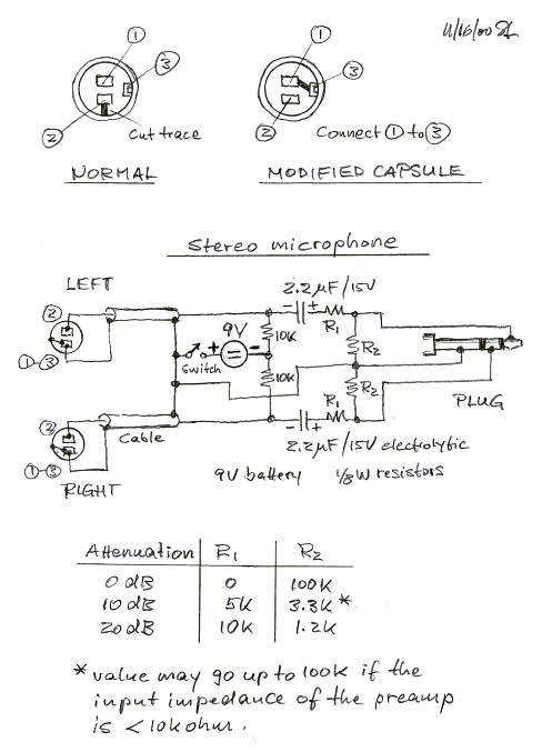
                              วิธีดัดแปลงไมค์คอนเดนเซอร์ แบบ2ขา เป็น แบบ3ขา

                              Panasonic WM-55A Capsule Modification > เวปต้นฉบับ
                              In order to make a 3-wire connection to a WM-55A103 capsule without damaging it, I make use of the 3 case-to-source traces on the rear PC board. I cut across the thin part of each of the 3 traces, but leave the wider parts intact to use as solder-to pads for the case wire connection. For the 3rd wire, I tin about 3/8" lead, and form it around a 1/4" TRS plug, which has the correct radius to match the capsule inside diameter. Next, I wet each of the 3 traces with a small solder blob. Lastly, I hold the bent wire over the 3 blobs, and use the 15W iron to press it down and into place (melting the blobs).

                              I use all 3 traces for the connection, so that it's strong. Because the WM-55A has vent holes in the back, I cannot use epoxy to pot the whole thing like I do on the WM-61A capsules.


                              Panasonic WM-61A Capsule Modification > เวปต้นฉบับ
                              First thing I do is cut away part of the aluminum rolled surround using my Radio Shack nippy cutters, cutting flush with the board so as not to scratch the copper trace. This exposes a bit of the copper trace. Prior to soldering to this copper, I tin it with the soldering iron and leave a tiny blob of solder on it.

                              I'm hooking up the mic capsules with Radio Shack "intercom" wire, which is 24 gauge stranded. I tin the wire tips that are going to be soldered to the capsule's existing pads, and leave about 2mm sticking out past the plastic insulation. To attach these two leads, I just press the tinned wire tip to the pad center, and hit it with the 15W soldering iron just long enough for the solder to melt and wick up the wire.

                              The 3rd wire that is going to be soldered to the copper trace, I bend at a right angle, so that at least 2mm of it is in contact with the tinned copper trace. Holding it to the capsule with mini pliers, I just hit the back of it with the iron until the solder melts together and it's attached.

                              The capsule is being held in a piece of clay brazing board into which I've drilled a 6mm hole, 4mm deep. I got this board from monsterslayer.com, a jewelry craft site.


                              ใครจะลองทำ แนะนำวงจรนี้

                              วงจรใช้งานได้จริง ออแอมป์ตัวเดียว ไม่ยุ่งยากซับซ้อน ทำใส่PCBเอนกประสงค์ก็ได้
                              ตัวไมค์คอนเดนเซอร์ ใช้ของยี่ห้อไรก็ได้
                              ไม่ได้มาดูนาน ขอการบ้าน+งานโีรงเรียนหมด แล้วจะ ซัดLM386 เข้า การ์ดออนบอร์ดซักที...

                              Comment


                              • อันนี้ของผมครับ GC LM3886TF NonInvert #1 อุปกรณ์บ้านๆ

                                Comment

                                Working...
                                X