Announcement

Collapse
No announcement yet.

D.I.Y.ตอน เครื่องขยายเสียง

Collapse
X
 
  • Filter
  • Time
  • Show
Clear All
new posts


  • Originally posted by ManiacMaew
    ถามคุณdracoVอีกแล้ว
    ถ้าใช้ไฟ+-12voltต้องเปลี่ยนค่าอะไหล่มั้ย

    คือบอร์ดภาคไฟที่มีอยู่มันใส่ic7812 7912ไว้อยู่จะได้ไม่ต้องหาเปลี่ยน icก็ไม่มีตัว15voltเก็บไว้
    ถ้าไม่ต้องเปลี่ยนค่าอะไหล่บนวงจรช่วงหลอดเลย จะได้ทำต่อเลยไม่ต้องไปหาซื้ออะไรเพิ่ม
    งั้นผมใช้ตามคุณแมวเลยละกัน (ใช้ไฟเลี้ยงวงจรDC +-12V) จะได้ลอกการบ้านคุณแมวง่ายหน่อย / แต่ถ้ามีเวลา ผมคงทำแบบไฟ30Vด้วย

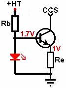
    ตรงส่วนCCSไฟเพลท ผมคงลองหลายแบบ เบสิคสุดก็Rตัวเดียว, แบบICตัวเดียว, แบบFET+IC (แต่ต้องหาJ112ก่อน)

    @ แมว
    คุณแมว ส่วนของอะหลั่ยชุดหลอด เผื่อระยะตัวRเป็นขนาดRN60นะ

    -- มีใครสนใจจะร่วมสนุกกับวงจรนี้เพิ่มหรือเปล่า --

    ---------------------------------

    อันนี้ที่ผมเคยถามก่อนหน้านี้ เอามาแปะรวมไว้ที่เดียวกัน จะได้หาง่ายหน่อย
    เอามาจาก หน้า48 #943
    Originally posted by keang
    @ dracoV
    1. หม้อแปลง +/- 12v ใช้กระแสเท่าไหร่
    2. ถ้าไม่ใช้ C อินพุท R2,3ควรใช้ค่าเท่าไหร่
    3. ถ้าใช้ R แทน Q1,IC1,R4 ต้องใช้Rค่าเท่าไหร่
    4. R7 อยู่หน้ากับหลัง R6 มีผลต่างด้านไหนบ้าง
    Originally posted by dracoV
    @keang
    1. หม้อแปลง +/- 12v ใช้กระแสเท่าไหร่
    สำหรับส่วนวงจรหลอดกระแสนิดเดียวไม่เกิน 30mA ส่วนของbuffer ถ้าใช้ตัวที่ผมทำก็เผื่อๆไว้ที่~200mA
    หม้อแปลงก็ ~350-400mA ก็พอ แต่ จะไปหนักที่ไฟ heater ~365mA
    ถ้าจะใช้ลูกเดียวทั้งวงจรก็~1A หรือใช้ 2ลูก ก็ 400mA กับ 500mA อย่างละลูกได้ครับ

    2. ถ้าไม่ใช้ C อินพุท R2,3ควรใช้ค่าเท่าไหร่
    สำหรับวงจรที่ใช้ไฟ +-15V ต้องใช้ C input ครับ ส่วนถ้าวงจร +30V, GND ก็ไม่ต้องใส่ C input และ/หรือ R2(1M)ก็ได้
    ใช้ R cathode bias อย่างเดียว แต่ก็ควรเพิ่ม R3 เป็น 470-560 ohm ครับ

    3. ถ้าใช้ R แทน Q1,IC1,R4 ต้องใช้Rค่าเท่าไหร่
    R ค่า~5k ครับ แต่วงจรนี้ไฟเพลทค่อนข้างต่ำ กระแสเพลท~1mA ถ้าใช้ R ไม่สเถียรเท่าไหร่
    แนะนำให้ใช้ CCS แบบในวงจรครับ แต่ก็ลองได้ R 5k แต่ต้องเพิ่มค่า C coupling เป็น~1uF-2.2uF ครับ

    4. R7 อยู่หน้ากับหลัง R6 มีผลต่างด้านไหนบ้าง
    ถ้าR6อยู่ก่อนก็จะ form กับ C3 เป็นfilter มีผลกับความถี่และเฟสครับ ทำให้เฟสสัญญาณหมุนไปหน่อย
    และจะformกับ R7เป็น voltage divider ลดvolt สัญญาณลงไปนิดหน่อยครับ
    จริงๆ R6 หน้าที่หลักเป็น gate stopper ลดการ oscillate ความถี่สูง
    โดยจะไปform กับ input capacitance ของส่วนinput ของbuffer เป็น low pass filterด้วย
    แนะนำให้ต่อตามวงจรครับ
    Last edited by keang; 28 Apr 2014, 19:59:02.

    Comment


    • เดี๋ยวงัด ของเก่ามารื้อทำใหม่บ้างดีกว่า...ได้เล่นด้วย
      (ของเก่ามีปัญหาเลยกองทิ้งไว้ก่อน)


      แต่ยังไม่เข้าใจการกำหนดแต่ละส่วนเท่าไหร่ครับ
      CCS ก็ยังไม่เข้าใจ แต่มองดูแล้ว ใช้Tr 100ma สบายเลย
      Last edited by tiger X-fi; 28 Apr 2014, 20:15:47.

      Comment


      • @ เสือ
        ถ้าจะเอามาต่อกับวงจรแบบ+/-15V ค่าอะหลั่ยจะเป็นตามนี้


        ขาแคโธด ด้วยทรานซิสเตอร์ : เอามาจาก หน้า56 #1109
        Originally posted by dracoV
        #1 จริงๆก็ได้น่ะนะ ถ้าอยากใส่ CCS ทั้งด้าน plate และ Cathode แต่ใช้ด้านเดียวพอน่ะครับ

        อ่ะ ถ้าต้องการแบบนี้ไปใส่ "cathode สำหรับวงจร +/-15V"
        Rb
        - ถ้าเอา +HT ไปต่อ gnd : ก็ 2.7k - 3.3k
        - ถ้าเอา +HT ไปต่อ +15V : ก็ 4.7k - 6k

        Re
        ใช้ 1k แต่ต้องเลือก LED ที่มี forward voltage ~1.7V (ปกติคือ LED สีแดง 3มม. ปกติ)
        แต่... เรารอคุณdracoVมาเฉลยครับกัน
        1. เราเปลี่ยนไฟเลี้ยงจาก +/-15V เป็น +/-12V : ฉะนั้นค่าตัวอะหลั่ยน่าจะเปลี่ยนแปลงนิดหน่อย
        2. ระหว่าง +HT "ต่อ gnd กับ "ต่อ +15V" : แบบไหนดีกว่ากัน

        J112 กลายเป็นแรร์ไอเท็มไปละ เบอร์แทนที่คุณdracoVเคยบอกไว้ คุณแมวก็บอกไม่มีขายแล้ว
        ฉะนั้น ผมว่าจะลองแบบนี้ : ขาเพลท...ใช้Rฟิกค่า / ขาแคโธด...ใช้วงจรนี้
        เรามาช่วยกันหา "ทรานซิสเตอร์NPN แบบตัวถังเหล็ก" ใช้กันเถอะ / ใครมีเบอร์ไรส่งประกวดบ้าง

        BC107A 200mA 300mW NPN Low Noise Audio Transistor TO-18 : datasheet
        2N2222A 800mA 500mW NPN Small Signal Transistor TO-18 : datasheet
        2N3053 700mA 40V NPN Planar Transistor TO-39 : datasheet

        -----------------------------------

        ขาเพลท ด้วยทรานซิสเตอร์ : เอามาจาก หน้า53 #1054
        Originally posted by dracoV
        @keang
        หมายถึงส่วนนี้หรือเปล่าครับ

        ส่วนนี้ก็คือส่วนของ CCS ครับ เป็นวงจร CCS แบบนึง
        + ข้อดี ประหยัด ใช้กับ B+ volt สูงๆได้โดยเลือก Tr ให้เหมาะสม
        - ข้อด้อย ทำลำบากหน่อยอุปกรณ์หลายตัว ไม่สเถียรมากนัก(แต่ก็ใช้ได้พอสมควร) ก็อาจมีปัญหา impedance roll off เร็วไปบ้าง
        และก็ Constant Current จะไม่เป๊ะนัก แปรตามอุปกรณ์ที่ใช้แต่ละตัว ถ้าให้ได้ค่าตรงหน่อยก็ต้องมาวัด/คำนวณกัน กับอุปกรณ์ที่ใช้จริง
        แต่ถ้าไม่ได้ต้องการเป๊ะนักก็ใช้ค่าประมาณ ก็ทำงานได้ครับ

        วงจรนี้ถ้าจะเพิ่มความสเถียรขึ้น มักจะใช้ Tr 2ตัว ตัวแรกเป็นชุดของ current regulator
        ตัวที่2เป็นบัฟเฟอร์ ลักษณะประมาณนี้


        ถ้าจะเอามาใช้ในวงจรที่ผมออกแบก็ได้ครับ
        - LED สีแดงใช้แบบมาตรฐาน 3มม. Forward voltage 1.7V
        - R 3k0(R emitter) ใช้ 1k แทน
        - R 3k3(blue LED) ใช้ 5k-7k ใช้ได้ ไม่ซีเรียสมาก ขึ้นกับ LED (blue led ในวงจร) ว่าต้องการกระแสเท่าไหร่
        - โดยปกติ C 470uF จะไม่ได้ใส่นะเพราะจะมีผลกับ current และ frequency response ในการใช้งานลักษณะนี้
        แต่ก็ไม่รู้น่ะนะ คนออกแบเขาคงทดลองมาแล้าว่าดี
        Last edited by keang; 28 Apr 2014, 22:41:03.

        Comment


        • 55555+
          คงไม่ต้องบอกมั๊งพี่...ผมเหล่เบอร์ไหนไว้ในใจ
          เน้นถูก
          Low Noise Audio Transistor ยิ่งทำให้น่าลอง
          -------------
          พวก BP npn 1A (to-39)
          เอามาทำบัฟเฟอร์แบบนี้ได้มั๊ยครับ

          ตั้ง idle current ประมาณ 100mA
          RS = V/A
          --------------


          http://www.tubecad.com/2009/09/blog0172.htm
          -------------
          Last edited by tiger X-fi; 29 Apr 2014, 05:45:55.

          Comment


          • > Basic Buffers

            One recurring question often seen is how to add a buffer to a circuit to prevent loading and loss of definition of the guitar sound. Buffers present a high impedance to the guitar pickup and have a low impedance output drive with a gain close to unity (unity gain = 1). This is an excellent addition in front of a vintage wah-wah or other circuit that can rob the signal of high frequency response. Buffers are simple, easy and cheap to construct. (Note: Any of these buffers could also be used on the output of an effect circuit.)


            Before we see the circuits let us look at a circuit fragment that may be required for some of the buffer variations. As shown to the left, the resistor/capacitor network provides a reference voltage that may be used to bias the transistor or opamp into the best operating range. The point marked "Vr" is connected to the point also notated as "Vr" on the buffer schematic. If there is a reference voltage already established in a circuit to which you are planning to add a buffered input, the existing Vr can be tapped and used for the buffer's reference.


            Probably the easiest buffer is the basic jfet common drain amplifier. The input impedance is determined by the value of R1 and is 1M as shown in this example. The value of R2 is not too critical and may be any value from 3.3k to 10k without much change in the sound. I prefer to use lower values since this allows more drive on the negative portion of the audio cycle where the only pull-down is the source resistor. This configuration has the least number of parts but is limited in that if the input voltage exceeds the gate-source forward voltage plus the bias voltage at the source, the signal will be clipped. This configuration is not normally useful with bipolar or mosfet transistors, which require a positive bias voltage (for N-type devices). Input impedance is approximately the value of R1. The output impedance will depend on the jfet but is on the order of a few hundred ohms.


            The basic jfet buffer shown in the last paragraph may be improved upon by connecting the gate resistor to a bias voltage instead of to ground. This allows the gate voltage to set the bias at the source to a higher vlaue which increases the headroom and allows a large signal input before clipping. The Vr point on this circuit connects to a bias voltage source as shown in the first paragraph. Input impedance is again approximately the value of R1. It could easily be increased to 10M or more for a cleaner sound with high impedance signal sources such as high-output humbuckers or piezo sensors with only a slight incerase in the thermal noise contributed by the higher value of R1.


            If you do not have a bias source available for Vr and you want to keep down the parts count, the gate bias can be set by a pair of resistors as shown in this example. The input impedance is the value of R1 paralleled by R3, or 500k ohms in this example, but you could easily increase their values to 2M to maintain the 1M input Z. This is the buffer that I used on the front end of the Dr. Quack Envelope Filter.


            If you substitute a mosfet transistor into the circuit of the last example and tweak the source and gate resistor values, it is essentially the AMZ Mosfet Booster in buffer mode. (See how these building blocks are useful?) A 9v zener diode (D1) is used for static protection on the mosfet gate. Mosfets have high capacitances between its electrodes and though there is no Miller Effect to multiply those capacitances, their value can nonetheless be high enough to cause high frequency rolloff depending on the characteristics of the individual mosfet transistors.


            A bipolar transistor may also be pressed into service if the input impedance does not have to be as high as that available from jfets. The advantage is that the bipolars usually have a lower output impedance and are generally easier to find. The disadvantage is the lower input impedance available as compared to fets.


            An alternate configuration is shown here that uses the voltage bias on the input in the same manner as the second jfet example above. This is the buffer used in the TS-series distortion boxes.


            An opamp is an even better buffer amplifier, though many believe they are somewhat colder sounding and more sterile than the transistor versions. The opamp gain is exactly unity and the output impedance is quite low; typically measured in tens of ohms instead of hundreds as with the transistors. It also has the lowest parts count of any of the simple buffers presented here.


            Voltage divider biasing is also possible with the opamp and the input impedance is calculated the same way as with the transistor versions similarly biased.


            This opamp buffer inverts the signal, which is useful when used in conjunction with following gain stages that also invert the signal and therefore would make the output non-inverted when compared to the input. This is important if the signal is mixed with other signals from the same source since cancellation could occur otherwise. The gain is unity and is set by R2/R1. The small 5pF capacitor is optional and gradually rolls off the high frequencies above the audible range. The input impedance of this circuit is the value of R1.


            Miscellaneous :
            Selection of the jfet or bipolar type is not critical, almost any transistor will work fine without problems. The gain of the transistor versions is slightly less than 1, probably 0.9 to 0.96. Transistors with higher hfe will be slightly closer to unity gain.

            The transistor circuits have very poor power supply noise rejection. Battery power works well with them but if used with an AC adapter, it must be well filtered and hum-free or the noise will be combined with the signal.

            For the jfet or mosfet circuits that use a single resistor on the gate for bias, you can increase the value of R1 to provide a higher input impedance. I typically use jfets on inputs and bipolars for output buffers where their better drive characteristics are needed.

            While this article just scratches the surface of buffer amplifiers, it presents enough basic circuits to handle 99% of effects requirements. Any of the building blocks above may be dropped into a circuit exactly as presented.


            --------------------------------------------------


            > Current amplifier and buffers

            Buffer amplifier
            Buffer amplifier is a circuit which transforms electrical impedance from one circuit to another. The main purpose of a buffer is to prevent the loading of a preceding circuit by the succeeding one. For example, a sensor may have the capability to produce a voltage or current corresponding to a particular physical quantity it sense but it may not have the power to drive circuitry it is connected to. In such situations a buffer can be used. A buffer when connected between the sensor and the succeeding circuitry easily drives the circuitry in terms of current or voltage according to the sensor output.Buffers are classified into voltage buffers and current buffers. The symbols of ideal voltage buffer and current buffer are shown in Fig 1 and Fig 2 respectively.

            - Fig 1 : Ideal voltage buffer symbol


            - Fig 2 : Ideal current buffer symbol


            >> Voltage buffer <<
            A circuit which transfers a voltage from a circuit with high output impedance to a circuit with low input impedance is call a voltage buffer. The voltage buffer connected between these two circuit prevents the low input impedance circuit ( second one) from loading the first one. Infinite input impedance, zero output impedance, absolute linearity, high speed etc are the features on an ideal voltage buffer.

            If the voltage is transferred from the first circuit to the second circuit without any change in amplitude, then such a circuit is called unity gain voltage buffer or voltage follower. The output voltage just tracks or follows the input voltage. The voltage gain of the voltage follower is unity (Av = 1). Even though there is no voltage gain, there will be a sufficient amount of gain in current. So when a voltage follower is connected between two circuit, it will transfer the voltage from first one to second one without any change in amplitude and drives the second circuit without loading the first circuit.

            A voltage buffer can be realized using opamp, BJT or MOSFET. Voltage follower using transistor (BJT) is shown in Fig 3. Voltage follower using BJT is also known as emitter follower. +Vcc is the transistor?s collector voltage, Vin is the input voltage, Vout is the output voltage and Re is the transistors emitter resistor.

            Voltage follower implemented using opamp is shown in Fig 2. This is done by applying full series negative feedback to the opamp ie; by connecting the output pin to the inverting input pin. Here the opamp is configured in non inverting mode (refer Figure 2). So the equation for gain is Av= 1 + (Rf/R1).

            Since output and inverting input are shorted ,Rf=0 .

            Since there is no R1 to ground, it can be considered as an open circuit and so R1 = ?

            There fore (Rf/R1) = (0/?) = 0.

            Therefore Voltage gain Av = 1 + (Rf/R1) = 1+0 =1.


            >> Current buffer <<
            Current buffer is a circuit that is used to transfer current from a low input impedance circuit to a circuit having high input impedance. The current buffer circuit connected in between the two circuits prevents the second circuit from loading the first circuit. The features of an ideal current buffer are infinite input impedance, zero output impedance, high linearity and fast response. A current buffer with unity gain (B=1) is called a unity gain current buffer or current follower. Here the output current just tracks or follows the input current. A current buffer can be realised using transistor (BJT or MOSFET).

            Current amplifier circuit
            A current amplifier circuit is a circuit which amplifies the input current by a fixed factor and feeds it to the succeeding circuit. A current amplifier is somewhat similar to a voltage buffer but the difference is that an ideal voltage buffer will try to deliver whatever current required by the load while keeping the input and output voltages same, where a current amplifier supplies the succeeding stage with a current that is a fixed multiple of the input current. A current amplifier can be realized using transistors.The schematic of a current amplifier circuit using transistors is shown in the figure below. Two transistors are used in this circuit. ?1 and ?2 are the current gains of transistors Q1 and Q2 respectively. Iin is the input current, Iout is the output current and+Vcc is the transistor T2?s collector voltage The equation for the output current is Iout = ?1 ?2 Iin .


            --------------------------------------------------


            > High-speed buffer comprises discrete transistors

            Circuits sometimes need a gain-of-one buffer to lower output impedance and prevent the load from interfering with the previous stage. For an application involving a 1.5-MHz, low-power transmitter and antenna, a Burr Brown BUF634 buffer IC would work, but a discrete transistor buffer may be more convenient and less expensive than the IC.


            Figure 1 shows the classic design of such a buffer. This circuit can drive a load as low as 200? with a peak output voltage of 2V. The maximum collector current of the transistors limits the output. You can use larger output transistors if your application requires more output current. Trimmer resistor R4 across the diodes is, however, a relatively expensive part, and you must adjust it to produce the correct bias current for Class AB operation. The adjustment is likely to drift over time.


            A simpler circuit, such as the one in Figure 2, uses currentmirror transistors Q1 and Q2 instead of diodes. Resistors R2 and R3 set the zero-signal bias current in the bias-transistor circuits. The current-mirror effect causes the current in the output transistors to be nearly equal to the current in the bias transistors?approximately 1.2 mA in this case. Because the current-gain-bandwidth product of the 2N3904 and 2N3906 transistors is 300 MHz, this circuit should work at 100 MHz or higher frequencies.

            At these frequencies, however, the circuit layout may be critical, and the slew rate, which is unknown, may limit usefulness. The offset of the circuit is approximately 0.1V, which is not a problem for this application because the circuit uses capacitive coupling through C1. If you use the buffer in the feedback loop of an op amp, the op amp can null the offset.


            You may want to monitor the current in the output transistors, so the circuit in Figure 3 adds 100 ohms resistors R3 and R4 and 10uF bypass capacitors C2 and C3 in the collectors of output transistors Q3 and Q4. The voltage across these resistors reveals the collector currents, which are nearly equal in the two output transistors, and is close to the value that the values of R1 and R2 predicted.
            Last edited by keang; 29 Apr 2014, 11:28:41.

            Comment


            • ใช้ไดโอดวางแบบตามภาพ
              ใช้ Zd หรือ LED ต้องกลับขั้วใช่มั๊ยครับ
              ยังงงๆอยู่

              Comment


              • ผมว่า รวมคำถามไว้ในโพสเดียวดีกว่า คุณdracoVจะได้ไม่ต้องดูหลายโพส

                สรุปว่า ในตอนนี้ "แมว, เสือ และ ผม" สนใจจะลองทำวงจรปรีหลอดแบบใช้ไฟเลี้ยง "+/- 15V" แต่เปลี่ยนไฟเลี้ยงเป็น "+/- 12V"
                แต่มีการเปลี่ยนแปลงบางส่วนด้วย จึงขอความเห็นและคำแนะนำจากคุณdracoVอีกครั้ง

                1. ใช้ไฟเลี้ยง "+/- 12V โดยใช้วงจรเดิมทั้งหมด" > ค่าอะหลั่ยในจุดไหนต้องแก้ไขบ้าง


                2. ถ้าทำ "CCSขาเพลท และ ใช้LEDสีแดงทั้ง2ตัว" ตามวงจรนี้ โดยใช้ไฟเลี้ยง "+/- 12V" > ค่าอะหลั่ยในจุดไหนต้องแก้ไขบ้าง


                3. ถ้าทำ "CCSขาแคโธด และ ใช้LEDสีแดง1ตัว" ตามวงจรนี้ โดยใช้ไฟเลี้ยง "+/- 12V" > ค่าอะหลั่ยในจุดไหนต้องแก้ไขบ้าง


                >> หมายเหตุ <<
                - ข้อ2และ3 คุณdracoVเคยแนะนำแล้วว่า ให้เลือกใช้แค่อย่างใดอย่างหนึ่งก็พอ
                - LEDสีแดง ขาทอง เดี๋ยวเอาจากผมไปใช้ / Rเฉพาะในวงจรหลอด เดี๋ยวรอดูค่าก่อน ถ้าผมมีเดี๋ยวเอาจากผมไปใช้
                Last edited by keang; 29 Apr 2014, 11:46:21.

                Comment


                • สร้างความเข้าใจกับหลอด
                  ก่อนที่จะออกแบบลากโหลดไลน์ ให้ดู Dissipation ก่อน
                  อย่าง 12aU7 Plate Dissipation 2.75W
                  (ในกราฟจะมีเส้นกั้นให้อยู่แล้ว)
                  กำหนด v/a ที่จะจ่ายให้ วงจร ไม่ให้เกินDissipation ที่กำหนด
                  แล้วค่อยลากเส้นโหลดไลน์ เพื่อที่ Rl Rk ต่อไป


                  -------------
                  เริ่มพอเข้าใจ
                  การใช้ Triode Calculator ก็ง่ายขึ้น
                  Tube-Specific Calculators
                  12AX7/ECC83 Dual Triode
                  http://www.ampbooks.com/home/amplifi...ulators/12AX7/
                  12AU7 Dual Triode
                  http://www.ampbooks.com/home/amplifi...ulators/12AU7/
                  12AY7 Dual Triode
                  http://www.ampbooks.com/home/amplifi...ulators/12AY7/
                  12AT7/ECC81 Dual Triode
                  http://www.ampbooks.com/home/amplifi...ulators/12AT7/
                  6SN7/12SN7 Dual Triode
                  http://www.ampbooks.com/home/amplifi...culators/6SN7/
                  5751 Dual Triode
                  http://www.ampbooks.com/home/amplifi...culators/5751/
                  6386 Dual Triode
                  http://www.ampbooks.com/home/amplifi...culators/6386/
                  Last edited by tiger X-fi; 29 Apr 2014, 09:15:13.

                  Comment


                  • ชอบรูปนี้

                    นกไม่เป็นไร เพราะไม่มีโหลด
                    แต่คนเป็นโหลดเต็มๆมาทั้ง โวลล์ ทั้งกระแส

                    Comment


                    • @ เสือ
                      - เจอของ 6DJ8 , 7308 , 6922 หรือเปล่าครับ แปะรวมในโพสเดียว แล้วทำเมนูที่หน้าแรกด้วย จะได้มีข้อมูลเบอร์ที่ใช้กันครบเลย

                      - นกมันเกาะแค่เส้นเดียว ก็เลยไม่ครบวงจร รอดจากการโดนไฟดูด
                      ส่วนคน มาครบทั้ง2เส้นก็รับไปเต็มๆ เค้าถึงกำชับเสมอว่า เวลาทำงานกับไฟให้ใส่รองเท้าตลอดเวลา จะได้ไม่แดนซ์ก่อนเวลาอันควร
                      แต่ถ้าเป็นพวกไฟสูงจัด มีโอกาสไฟอันร้อนแรงวิ่งทะลุรองเท้าได้ ระบบป้องกันต้องสูงขึ้นอีก

                      ---------------------------------

                      @ เสือ , แมว : ลองวงจรนี้มั๊ย (เอามาจากเรื่องBUFFER ที่โพสไว้ข้างบน)
                      ทรานซิสเตอร์ในวงจรเป็นTO-92 ถ้าชอบตัวเหล็กTO-18ก็เปลี่ยนเบอร์แทน


                      You may want to monitor the current in the output transistors, so the circuit in Figure 3 adds 100 ohms resistors R3 and R4 and 10uF bypass capacitors C2 and C3 in the collectors of output transistors Q3 and Q4. The voltage across these resistors reveals the collector currents, which are nearly equal in the two output transistors, and is close to the value that the values of R1 and R2 predicted.
                      Last edited by keang; 29 Apr 2014, 11:37:49.

                      Comment


                      • > What do the different classes of amplification mean ?

                        You may have seen terms such as ?Class D? or ?Class H? or ?Class AB? and wondered what they mean and whether they have any effect on sound quality. Most of these classes are defined by the Institute of Electrical and Electronic Engineers (IEEE), although for marketing purposes some manufacturers come up with their own letters for particular proprietary variations. We?ll take a look at each of the common amp classes.

                        An amplifier circuit requires one or more active devices to be able to boost a signal. An active device is a component that uses a small signal voltage or current to control a larger current flow, like an electronic valve. It could be a bipolar transistor, a field-effect transistor (FET), or a vacuum tube. Audio amplifier circuits commonly use multiple active devices, depending on the nature of the circuit?s function. The amplifier classes? definitions are based primarily on how the active devices operate on the signal waveform. For the sake of simplicity, we?ll use only bipolar transistors in the circuit examples.


                        Class A
                        In a Class A amp circuit, the transistor or transistors each conduct current throughout the signal waveform. Because of this, they must be biased (turned partially on) at quiescence (at rest, with no signal) so that their output voltage is about midway between the positive and negative limits.

                        Class A circuits can be great for audio fidelity, as there is no need to make transitions between transistors for different parts of the waveform, so there is nothing to cause a discontinuity. The downside is the circuit?s poor electrical efficiency. Because of this, Class A is used mostly in small-signal circuits and very, very rarely in power amp output circuits, with the exception of some boutique ?high-end? audio amplifiers. A class A power amp of even a moderate power rating would emit a great amount of heat and would require a very large power supply and huge heat sinks. It could help keep your house warm in winter, though!

                        This circuit is a single-transistor class A amplifier stage in a common-emitter arrangement, which provides voltage gain but also inverts the polarity of the signal. (The arrows show how the signal causes variations in the current flow through the circuit.)


                        This circuit is a class A stage in a common-collector arrangement (often called an emitter follower), which does not provide voltage gain but does increase the available output current. Thus, it is useful as a buffer, or voltage follower.


                        Class B
                        This topology improves efficiency because the transistor is biased at cutoff. That means that at quiescence?at rest?the transistor conducts no current. As a result, it responds only to signal voltage swings in one direction, either positive or negative.

                        In order to reproduce the entire signal waveform, then, we need at least two transistors: one for the positive side of the signal and one for the negative. Typically, designs that use bipolar transistors employ a complementary arrangement of NPN for one signal polarity and PNP for the other. (A few decades ago, when PNP power transistor technology and quality lagged behind that of NPN, it was common for design engineers to use a ?quasi-complementary? arrangement of NPN devices for both the positive and negative parts of the signal.) The current drawn from the power supply by each transistor is then proportional to the signal voltage. No signal, no current; small signal, small current; large signal, large current. High efficiency. All is great ? except that it generally doesn?t quite work as well as that.

                        The problem lies in the transitions between the positive and negative parts of the audio signal. Bipolar transistors arranged this way require a bit of signal voltage just to start to turn on?about 0.6 to 0.7 volt in either direction. Below this threshold, there won?t be enough signal level to turn either transistor on, and even signals that exceed 0.6 volt will be distorted by the discontinuity. This phenomenon is called crossover distortion (named for the crossing over between negative and positive, not for circuits that divide the audio spectrum), and it is particularly nasty sounding; unlike clipping distortion, it affects all signals, but the smaller ones it affects proportionally more severely.


                        There is a solution to this quandary, and it?s called Class AB because it combines some of the characteristics of both Classes A and B. It uses the basic Class B circuit but biases the transistors slightly on at quiescence. The transistors thus conduct a little bit of current with no signal present, but the crossover transitions are much smoother. The proper amount of bias is a balance between keeping the quiescent current low on the one hand and minimizing crossover non-linearity on the other.


                        Class C
                        In Class C, the transistor is biased ?below cutoff? so that it conducts only during a smaller portion of the signal waveform. This is used in single-carrier radio-frequency amplification, and the short pulse of conduction is usually used to excite a resonant circuit. The efficiency can be extremely high, but it has no practical application in audio.

                        Class D
                        Class D amplification has been getting much attention in recent years as manufacturers seek ways of achieving ever-higher power and/or efficiency. Unlike Classes A, B, and AB, Class D is completely non-linear. It uses pulse-width modulation to actuate switching transistors and create a high-power pulse train that alternates between a pair of positive and negative rail voltages. The pulse width is proportional to the audio signal voltage. A passive low-pass filter?the "reconstruction" filter?on the output smoothes the pulse train back into an audio signal.


                        Because the switching transistors alternate between being completely on (the transistor has high current flow through it, but nearly zero voltage across it) and completely off (high voltage across it, but zero current through it), the power lost in them is extremely low. The heat generated in normal operation, then, is quite low, and the electrical efficiency is very high.

                        Class D does not mean or stand for ?digital.? In fact, most class D amps are completely analog, with analog modulation. The PL380 was QSC?s first stand-alone class D amplifier, and now it is joined by the CXD and PLD Series amplifiers. The amp modules in the K Family (K, KW, and KLA Series) powered loudspeakers are class D.

                        Comment


                        • ดาต้าหลอด ผมใช้ตัวนี้ครับ รู้สึกว่าแปะไว้หน้าแรกแล้วครับพี่
                          http://www.shinjo.info/frank/sheetsE.html

                          Comment


                          • การทำงานของทรานซิสเตอร์ เข้าใจไม่ยาก
                            > Transistor Tutorial

                            Comment


                            • packages

                              Comment


                              • คิดอีกที เริ่มลังเลกับเรื่องไฟเลี้ยงวงจรหลอด / ถ้าดูกราฟของหลอด จะเริ่มต้นที่ไฟต่ำสุด คือ 100V+
                                ถ้าใช้ไฟเลี้ยงน้อยไป เหมือนเป็นการลดจุดดีจุดเด่นของความเป็นหลอด รึเปล่านะ

                                Comment

                                Working...
                                X