 Tweet
Tweet
หม้อแปลงทรอน นี้สั่งพันยังไงครับ มีเบอร์ เขามั้ย? หรือมีหน้าเว็บมั้ย ผมหาไม่เจอ
-
-
tron
T .0-2222-3495 , 0-2226-4203, 0-2623-8658
ชนาธิป สุรชัยสิทธิกุล
Mobile : +6681 558 0010Last edited by jinn; 20 Feb 2012, 22:11:59.Comment
-
ขอบคุณครับComment
-
-
ของเดิม เครื่องที่เคยประกอบไว้ ที่ขั้วrcaเฉพาะขั้วกราวน์ทำยังงัย ต่อสายขั้วกราวน์ยังงัย
เคยถ่ายรูปไว้หรือเปล่าComment
-
-
-
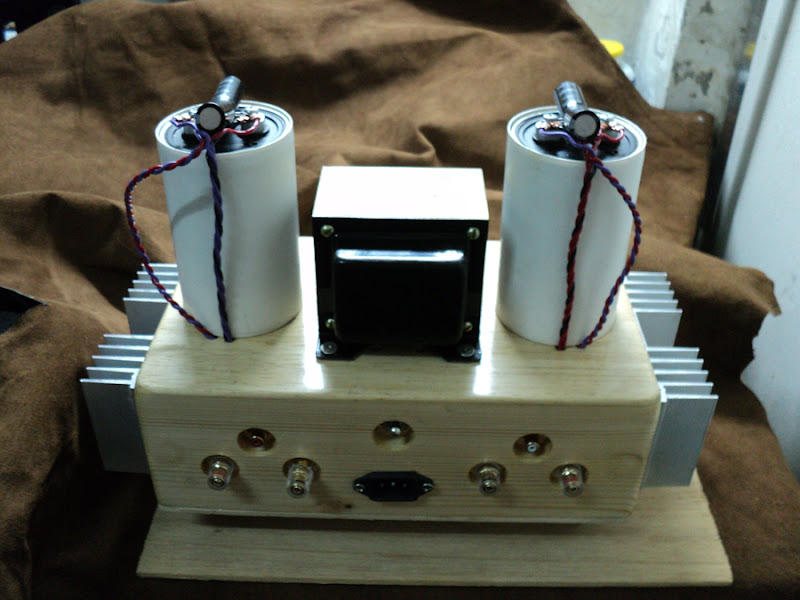
เอามาต่อฟังเสียง....ป็อก แป๊ก ....ดู


ตอนเปิดหน่วงประมาณ5 วินาที / ใช้ไฟ 12 v.
แก้ไม่ได้...ครับ / ตอนเปิดคอม / asus stx ก็ยังมีเสียง ปุ๊กอยูู่
ต่อกับ cd player เวลาเล่น หยุด - เปลี่ยนแทรค กันยังมีเสียง ปุ๊กอยู่ ....
ตัวป้องกันลำโพง ......ที่ผมลอง ช่วยในส่วนนี้ .....ไม่ได้ครับ....
เสียงที่ต่อโดย ถือว่าใช้ได้......รายละเอียดไม่หายไปมาก....เท่าไร ( พอรับได้ )
โมหน่อย...น่าจะผ่าน....
....................................................................................................
เพ่เสือ......เราเท่ ...สะไม่มี.....
Last edited by jinn; 21 Feb 2012, 23:07:33.Comment
-
!! เพ่เสือ !!
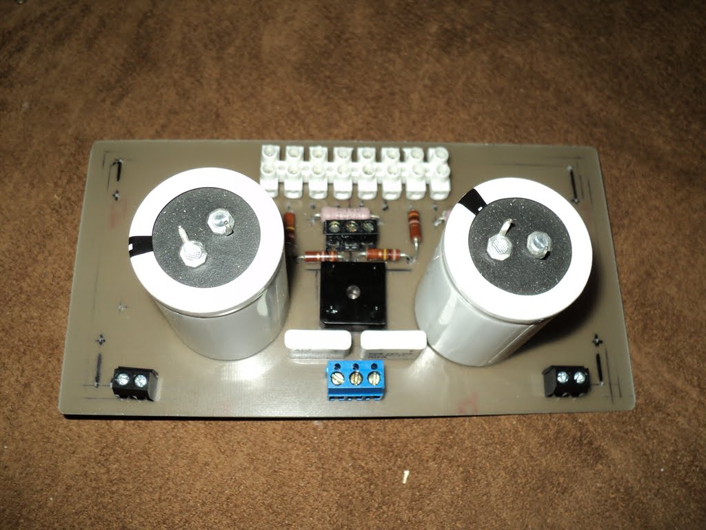
วงจรหลอดตัวนี้

ต่อแบบนี้ง่ายกว่ามั๊ย (รูปข้างบนก็บอกวิธีต่อขาอะหลั่ยแต่ละตัวไว้อยู่แล้ว)
อะหลั่ยที่จะลองก็น่าจะมีแค่2ตัว Cเอ้าท์พุท กับ Cฟิลเตอร์
- Cเอ้าท์พุท : วางบนpcb พื้นที่ก็กว้างขวางพอให้ใส่Cฟิลม์บิ๊กเบิ้มได้ทุกตัวอยู่แล้ว
- Cฟิลเตอร์ : ยังงัยก็ต้องต่อสายไฟอยู่แล้ว ยาวขึ้นอีกนิดก็ไม่น่าเป็นไร
( วงจรที่คุณjinnกับคุณLove HiFiทำ ก็ทำแบบนี้ได้เหมือนกัน )


ขยับหลอด ขยับCเอ้าท์พุทไปใกล้ๆRCAเอ้าท์พุท
ถ้ามั่นใจว่าตัวCที่ใช้ ให้เสียงถูกใจเต็ม100 ให้มิติเวทีเสียงเต็ม100 ก็บัดกรีขาCที่ขั้วRCAเลย
เมินสายสัญญาณที่จะใช้ช่วยจูนเสียง เมินสายสัญญาณที่จะใช้ช่วยเรื่องมิติเวทีเสียง ทิ้งไปได้เลย

ต่อแบบนี้ดูแล้วน่าจะเหนื่อยกว่า
 Last edited by keang; 21 Feb 2012, 16:29:24.
Comment
-
ผมก็ต่อกับ 1875 ก็ไม่หายครับช่วยไม่ได้ครับ ผมยังไม่เข้าใจการทำงานของป้องกันลำโพงครับ คือถ้ามีไฟเกินมามันจะตัดให้เลยใช่ไหมครับ แบบเซฟทีคัต เลยใช่ไหมครับ เรียกว่ามีมันอยู่ลำโพงไม่พังใช่ไหมครับOriginally posted by jinn View Post
ของผมของนัฐพงษ์ยังตัังเวลาให้หน่วงไม่เป็นเลยครับ มันหน่วงให้แค่ 1 วิเองครับComment
-
Speaker protect
วงจรเป็นอีกวงจรที่สำคัญมาก เนื่องจากการทำงานของแอมป์ขับซับฯจะใกล้ ๆ กับไฟ DC บางครั้งอาจเกิดการผิดพลาดของวงจรทำให้เกิดไฟ DC หลุดรอด ออกไปสู่ลำโพง สร้างความเสียหายแก่เงินในกระเป๋าเราอีก ... อิอิ วงจรนี้เรียกว่า วงจรป้องกันลำโพง โดยหน้าที่หลักของมันจะมี 2 อย่างคือ 1 ป้องกันเสียง ตุ๊บ ขณะเปิดแอมป์ และ 2 ป้องกันไฟ DC ไปสู้สำโพงอันแสนป๋องแป่วของเรา

........................................................................................................
วงจร[PDF]
?ป้องกันลำโพงนั้นสำคัญไฉน
Comment
-
> Tubelover Indonesia
ECC86 Low-Power Supply CD Buffer (ไม่จำกัดแค่CD Player จะเอาไปใส่กับอะไรก็ได้)

Comment
-
เด๋ว ทำเล่นอีกตัว ดีก่า .....เสียงเมามันส์สสสสส.....แน่ ห้า.....ห้า.........ห้า.....Originally posted by keang View Post


ปล.
เมื่อวันเสาร์ เห็นเครื่องเล่น CD player มีหลอด 12au7 / 2 ตัวอยู่เครื่อง
จำไม่ได้แล้ว....ชื่อ brand อะไร / ตอนแรก.....เห็นแล้ว แปลกตา....สวยดีแท้.........Last edited by jinn; 21 Feb 2012, 17:23:31.Comment
-
--------------------------------------------
ใครมีใจรักจะเล่นหลอด อยากเข้าใจตัวหลอดมากขึ้น ควรอ่านให้หมดน่ะ
--------------------------------------------
"RAM Tube Works" by Roger A. Modjeski (ผู้ผลิตเครื่องเสียงยี่ห้อMusic Reference)
Music Reference and RAM Tube Works


Music Reference (MR) was founded in 1980 in Santa Barbara by Roger A. Modjeski after the completion of 3 years as Chief Engineer at Harold Beveridge, Inc. There he designed the RM-1 preamp and the RM-3 Crossover while apprenticing under Mr. Beveridge in the field of Electrostatic Loudspeaker design. The first product for MR was the RM-4 tube pre-preamp, which set new standards for low noise amplification of moving coil cartridges.
The RM-5 preamp was released in 1981 and the RM-9 power amp in 1986 completing a line of high performance tube amplification products. These products enjoyed many years at top rated components by Stereophile Magazine, with the RM-9 being rated class A with "$$$" (a rating equal to products costing ten times as much). In addition to value and fine performance, MR products are known for their ease of use, reliability and longevity. From a sales point of view the products have a long market life with the RM-5 being produced over a 20-year period with only minor changes.
The RM-10 was introduced in 1996 adding a low cost 40-watt power amp to the line. The RM-200 replaced the RM-9 in 1998 as our 100-watt fully balanced amplifier. All enjoy dedicated customers with some owning several pieces. The products have become collector items and enjoy good resale value on the used market. It has been often said "For a small company, you have a big voice in the industry".
Ram Tube Works (RTW) was established in 1982 and was the first company to offer premium tubes tested by computer. Over the years several other companies have tried to take our market and failed. None has developed a computer tester to match ours. We now, once again, have this market to ourselves and it awaits our expansion to deeper levels. MR and RTW products are known worldwide. The RM-200 is the #1 amplifier in Greece (which has a very active audiophile market). We have enjoyed significant sales in Taiwan, Singapore, Japan and Europe.
Music Reference RM-5

C4 with 6H30 dual triode, 6C4 single triodes, and 0B2 regulator tubes from RAM tubeworks

C4 preamp and EM7 amp with Twisted-pair interconnects and solid copper enameled speaker cables

--------------------------------------------
The Virtues of Power Tube Matching by Roger A. Modjeski
My experience gained from testing thousands of EL-34's, 6550's, KT-88's, and other tubes has produced a wide bell curve of the two most important parameters, Bias and Transconductance. The center of this curve is the "bogey" value that the manufacturer is trying to hit, and the ends show the cutoff points of what he is willing to allow out of the factory. The tubes at the ends are still perfectly functional, but may not work well in all amplifiers, and will certainly not work well if mated with another from the opposite end of the curve.
Some amplifiers do not have enough range on the bias pots to handle the range of tubes so that selection-must be made from a particular part of the curve to ever achieve bias.
In the "good old days," I'm told, the spread of values was much less, allowing reasonable performance with random selection. Today, random selection is strongly not recommended-I'll tell you why.
Looking at bias voltage in a typical batch of EL-34's from the best producer, it will typically range from -32 to -42 volts for 50mA of plate current. At a typical transconductance for 7000 umhos (7 mA/volt) the 10 volt difference will cause a 70 mA bias difference. Obviously, one tube will be on and the other cut off if they are biased with the same adjustment pot. I match the bias voltage to. 0.5 volts or better, and thus have only a 3.5 mA (0.3 x 7 mA/v) difference in plate currents, which is only 4% maximum at 50 mA.
Now, those of you with individual bias adjustments are probably thinking that you've got it all handled because you can adjust for these different grid voltages. Well, you can-but in doing so, you will create a greater problem.
Say you put a -32 volt tube in one socket of a push-pull pair and a -42v in the other and bias them so that their currents are equal. Unless you can also adjust the a.c. balance of the driver to provide 32v of drive to one and 42v to the other, you will have very unsymmetrical clipping and reduced power output.
In most amplifiers with a.c. balance, the range of adjustment is nowhere near this, as that adjustment is meant to balance the driver and not current for widely unmatched output tubes.
In our modern, larger amplifiers, multiple pairs are used in push-pull parallel to achieve higher powers. It takes four of the popular output tubes to safely attain 100 watts, and here matching is even more critical.
To fully appreciate the problem, you must know a bit about the operation of a tube output stage. In push-pull parallel, we have four (or more) tubes connected so that two (in parallel) handle the positive half of the output signal, and the other two handle the other half. Even if you do find two tubes which are 5v off, there will be 35 mA different in bias current, which is still intolerable.
Ideally, they are all biased at the same negative grid voltage and have the same current through them. As we apply positive signal, the grid voltage goes up on the first pair of tubes, raising their current in a shared manner. For this to happen, they must have the same transconductance (Gm), which is the measure of how many mA/volt the plate current changes. Imagine if one has 7000 umhos (7mA/v) and its partner has 5000 umhos (5mA/v).
By the time they hit 0v (coming up from the -35v bias), one is conducting 175mA and the other is conducting 245 mA, which is neither fair, nor a good idea. Now imagine if these tubes didn't even start at the same bias, but were adjusted by individual pots to -32v and -42v as per the manufacturer's method of achieving equal bias currents. What then happens is that the -32v tube clamps the drive when it hits 32v (0 on the grid), and the -42v tube's grid never gets higher than -10v. Since most amplifiers require bringing the grid up to zero for full power, with unmatched tubes, you will never attain maximum performance.
Here's an analogy for the mechanically-minded. Imagine a VW-type engine where the cylinders are opposed and made separately, and the manufacturer puts together engines where the pistons, rods, and cylinders are not very uniform. In this engine there is only one arm on the crank (like the driver in our amplifier), and all the rods are connected to it so that they all have the same length of throw. One "pair" of pistons should top out together when the other pair hits bottom. If any of them has a short rod, it will achieve less compression and therefore less power. If he matched the rods and selected cylinders of the same bore, he would then get equal power per constraint of that one crank, as we have with our single (symmetrical) drive voltage. With unequal push rods, we're going to end up with very different compressions at the end of the stroke, and thus very different output power from each cylinder.
Fortunately, this nasty problem has a solution-simply match the tubes for Bias, and Gm, and use one bias adjustment. Then the amplifier will be working at its best, and the consumer will have the simplest possible set-up.
At RAM Tube Works, we match for Bias within 4% and Gm within 8%. We provide tubes in any size sets at no extra charge. We give you the full data for each tube so you may see the matching for yourself. We also reject tubes which have high grid leakage (gas), low power output, unreasonable bias or Gm, and other flaws.
We guarantee our tubes for ninety (90) days, and your satisfaction for as long as you are our customer.
--------------------------------------------
Modjeski Reference Tubes
You wouldn't choose instant coffee to make cappuccino, would you? Nor would you choose diet margarine to make a pound cake. At least I hope you wouldn't if you had invited me to dinner. But that has been the predicament of the owners of fine tube audio equipment when they needed replacement tubes.
Most of the tubes available, even from the best manufacturers, are incapable of delivering the sumptuous qualities and musical detail that distinguish tube equipment at its best.
Through personally testing tubes, I found that measuring the noise voltage alone was insufficient for determining the acceptability of tubes. Taking two tubes that measured the same noise voltage I could still distinguish a difference, I defined this quality of noise as RAM factor, and designed a circuit to measure it. For the first time it was possible to objectively isolate and measure one of the key variables that accounted for sonic differences and variation heretofore unexplained.
Even after the discovery of the RAM factor I still had a sizable logistics problem. Testing thousands of tubes to my exacting standards, including repeated measurements at different times, at different temperatures, in addition to "burn in" time, was taking many days to produce the small percentage of tubes which qualified for listening to music.
Solving that problem took another year. I had to develop my own computer-controlled testing system, This system is run by a specially modified Apple II+ computer which tests 128 tubes simultaneously. The computer takes 200 different readings from each tube, averages the readings and records them.
After the tubes are tested, the computer prints a label for each one with all of the test results for that particular tube. Furthermore, the grading of the tubes is done by sections, unless the tube is destined for a head amp, where it must rate a perfect "A" for parallel operation. Typically, this "A" grade is the best tube in 10 tested. The "SA" grade is the best one out of 100 tested.
The double letter indicates the separate ratings of sections 1 and 2 in the tube. When we grade a tube, we grade it by the lower rating of the two sections. Our letter grade designations represent the guaranteed minimum performance. Even our tubes with ratings such as "BB" and "CC" are good choices for use in high level stages and cathode followers and are distinctly better than random untested tubes.
RAM TUBE WORKS also provides computer-tested and matched tubes for power amplifiers. Front end tubes are normally dual triodes and are similar to pre-amp tubes. Driver tubes are graded for tight gain matching and operating bias so that they enhance performance in push-pull balanced circuits. Output tubes are computer matched for bias current and transconductance (Gain). This is essential for amplifiers (Dynas and others) with no AC (Gain) or DC (Bias) balance controls. You will be amazed by the sound of your amplifier equipped with computer-balanced, matched tubes.
Each tube is individually serial-numbered on the box and on the glass. Tubes are warranteed for 90 days to meet specifications. Any warranty claims MUST include the original box upon return.
--------------------------------------------
The Suitability of the 6DJ8 for Audio by Roger A Modjeski
About The Author
Roger Modjeski received a BS in Electrical Engineering in 1973 from the University of Virginia and was a teaching assistant while studying for his Masters at Stanford in 1975. He has been active in electronics since the age of five watching his dad build a Heathkit Williamson. Prior to starting Ram Tube Works and Music Reference in 1980, he opened a high-end retail store where he met and later worked for Harold Beveridge. His other interests are music theory, piano, singing, building musical instruments, solar energy, architecture, and understanding how things work.
This article attempts to correct a few misconceptions about some of the popular dual triodes used in audio amplification. "Through my work developing and running the computer tube tester at Ram Tube Works, I've evaluated dozens of each type, from every manufacturer currently in production and many of the classics. I have developed circuits for both home audio and musical instruments. I keep a little collection of these classics to test whether my equipment works with both old and new tubes."
The guitar player seeks to add pleasant distortion, whereas the home audio listener generally requires none. Remember that the solo player can use distortion to enhance that instrument. Yet the same distortion, added again, destroys the reproduction of such a recording.
Preamplification
Once upon a time there was only the 12AX7. This is not entirely true. There existed previously an array of reasonably low-noise octal-based triodes (there were some four-pin models, but let?s not go that far back) including the single triodes 6J5 (ต = 20) and 6F5 (ต = 100), along with the twin types 6SN7 (ต = 20) and 6SL7 (ต = 70). The miniature types 12AU7 (ต = 17), 12AT7 (ต = 60), and the ubiquitous 12AX7 (ต = 100) appeared after WWII. The 6DJ8/6922 (ต = 33) appeared in the late 1960's designed for use in color TV tuners. Textronics and others used them in oscilloscopes and other high performance test equipment. In my research for a very quiet phono input/head amp tube I found it to be the best choice due to it's linearity and high transconductance. I used 12 of them for my first commerical design effort with Harold Beveridge, Inc.
The RM-1 preamp that resulted had, and still has, the quietest phono stage extant with tube input. Its design led me to investigate the physics behind a low-noise tube. I also found that the 6DJ8 had better linearity (lower distortion), wider bandwidth, and better ability to drive the output jack with a strong low-impedance signal, which is preferable when you use a long or high-capacitance cable.
The 6DJ8's transconductance parameter is highly prized, but also disputed. To give me an intuitive handle on transconductance (gm), Bev (Harold Beveridge) said, "We, and many Europeans, do not generally use ตmphos (micro-mhos) as most American engineers do. We say, ?one milliamp per volt for transconductance of one millimho? (which is 1,000 ตmphos)."
I prefer this method of expression because it better describes what really occurs in the tube. A 1V change in the grid causing a 1mA change in the plate produces a transconductance of 1mA/V. A high-transconductance (high-gm) tube, such as the 6DJ8, has a gm of 10-13mA/V (i.e., 10,000-13,000 ตmhos). But a triode with high gm is not necessarily a high voltage-gain triode; the 6DJ8 has almost 10x the gm of the 12AX7, but one-third the mu (voltage gain).
Transconductance in triodes and pentodes increases quite dramatically with plate current, which is a source of distortion because it increases as the signal swings negative and decreases as it swings positive (at the plate). This is the basic distortion mechanism in all active devices, vacuum and solid state.
Two Other Factors
In typical triode circuits mu becomes the controlling amplification factor or gain and is easy to spot in the data books since it has not units. It is the simple ratio of signal Vout/Vin, and is given along with a particular set of operating conditions of plate voltage, plate current, and grid bias. Mu will vary with these, but not much (or so hope those of us who desire low-distortion, nonfeedback amplifiers). Instantaneous voltage gain (mu) must be constant to achieve low distortion. When an amplifier is linear, its voltage gain is constant at all levels and frequencies of interest.
In the data books the mu value also assumes an infinite external plate resistance, which is the only way to isolate the tube from the effects of the circuit and provide a useful value. The RCA Receiving Tube Manual includes a section, "Resistance-coupled Amplifiers,"
which includes the values of gain, maximum output voltages, and other interesting data for the popular voltage amplifiers.
The "current source" camp approaches that ideal gain given by mu. I do not use current sources, which can introduce noise, complicate circuits, often employ transistors that must be protected from high voltages, and don?t help much in real-world situations. My first RM-4 headamp prototypes contained quiet transistor current sources, but I abandoned them for low-noise resistive plate loads.
When you consider the load that follows the plate (which we have tried to please with an infinite-impedance current source), much of the "infinite impedance" is lost. A high plate supply voltage can usually allow a plate resistor 5-10x the internal plate resistance (rp) of
the tube, which is generally high enough; beyond that figure little is gained. The triode's internal resistance is its saving grace and makes a triode an inherently linear amplifier.
Predicting Distortion
In a graphical representation of these three qualities, gm rp and mu, as they vary with plate current, gm rises markedly with rising plate current, rp falls proportionately, and the product remains virtually constant. Once I became aware of this, I knew what to look for in a low-distortion triode. Yet, I was amazed how difficult it was to find those three curves, which are not included in the RC series RCA manual or any poplar American manual, except the commercial Tung-Sol. They are often contained in the European manuals, particularly those by Philips and Telefunken.
I first seriously considered this question of simple distortion in 1978 in a single triode stage and realized that distortion is due simply to the change of mu with signal. Comparing the curves of the 12AX7 and 6DJ8 clearly revealed the superiority of the 6DJ8 for constancy of mu. Building them in typical circuits confirmed this.
Most designers like to talk about the even spacing of the plate curves, as given in RCA, as a measure of linearity, probably because that is all they have to work with. I concluded that for the small signals we see in preamplifiers the curves lacked the resolution to accurately predict the distortion.
Remember that in a typical stage the plate current swings only a few percent. Yet the closest-spaced plate curves for the 12AX7 are 100% apart and are only approximate. I believe they were hand drawn from a curve tracer, or by tracing a photograph of the screen. Their main function is to allow circuit designers to figure voltage and resistance values to establish an operating point. Be careful with this method of analysis for predicting distortion.
Locating Good Tubes
In 1985 I learned that the Tungsram Lamp Works in Hungary was quitting the tube business. Only a year or two before I secured a reliable line of supply through their US office. That was the only sure way to get factory-fresh tubes that were not falsely marked or some other tube selector?s rejects. When that line of supply dried up, I was forced to return to general distributors, who buy direct from the factory or through other distributors.
Basically, the tube distributor has a bit of a hard lot finding the most reliable quality and authenticity at the best prices. Factories often do not store inventories, as they will build even a popular type such as the 12AX7 only once or twice a year due to the time required to set up a type in the factory and retrain workers. On my visit to the Yugoslavian factory (Ei), I learned that assemblers required as many as six weeks to reach full speed on a type they had built before.
When a factory such as Ei or Tungsram manufactures a popular tube, it generally has contracts for the majority of its production run. These firm orders plus inventory requirements determine the size of the run and the quantities of raw materials needed for that tube. Many of the materials are type-specific, that is, the diameter of grid wire, size of cathode sleeve, width of steel on the roll that becomes formed plates, and glass tubing diameter which is cut to length at the factory.
After these tubes roll off the line they are sent to various distributors, who have estimated their annual sales and ordered accordingly. Sales are often guesswork, customers come and go; one is fat on a product and the other is lean by the end of the year. Sometimes everyone runs out of a particular brand and is forced to go hunting. That?s when the really weird stuff shows up in the market, such as the fake Tungsram 6DJ8s that found their way to Ram Tube Works and into my RM-1 in 1983.
Imposter Revealed
By this time I knew how to identify a Tungsram tube by looking beyond the glass to the internals to identify the maker. I had seen too many Russian tubes marked "made in W. Germany" or "made in England" to be fooled by the paint on the glass. Only Tungsram tubes, to my knowledge, had an easily visible, shinny silver square with a two-digit embossed number attached to the getter post. So, my tubes really looked like 6DJ8s but I noticed they acted a bit schizophrenic.
In some circuits they behaved very much like 6DJ8s, but not in others. I suspected the difference had to do with plate current, so I rigged up my chart recorder to plot mu versus plate current and gm versus plate current. In a line-up of four samples of four manufacturers, the fake (market F. Tungs on the graph) showed itself without a doubt (Fig. 1). This impostor had a decidedly variable mu curve, which we do not want at all for audio.
I encourage you to study the chart carefully. The top four curves show mu versus plate current from zero to 6mA. Note that mu is very constant from 0.4mA upward in the top two (USSR and Real Tungsram), and a bit lower and not as flat on the Procom. The F Tungs is noticeable for its very low mu that rises from less than 10 at 0.5mA to almost 30 at 6mA.
After seeing these curves, I was quite comfortable running a real 6DJ8 anywhere between 0.5mA and the point of maximum dissipation. I later found it wise to keep the dissipation down to 0.5W/section for good reliability. The 1.8W/section specification is far too ambitious for a tube with such a small plate and closely spaced grid.
The lower set of curves shows the actual transconductance versus plate current. Note that the scales are log. Since the transconductance has reached 50% of its maximum (on my curves) at 2mA, I do not see a need to go much further with raising the plate current. It seems to be headed across the 10,000 ตmho mark if we go to 15mA, as the spec sheet suggests. But at 15mA I would have a plate voltage of only 33V to stay in my 0.5W dissipation limit.
Sylvania specifies 15mA at 90V, resulting in 1.35W/section. I remember burning my fingers all too often when replacing 6DJ8s in color TV tuners. Sometimes application engineers get carried away. In this case, they dealt with the "devil of reliability" for removing that last bit of snow in the picture. Read the notes carefully to see Sylvania?s concerns about voltages and currents.
Now we must create the application note for an existing tube in an entirely new area. For me, this is where the fun starts. Remember that the cascode circuit for which the 6DJ8 was designed works with microvolt inputs. We employ volt inputs in line stages and drivers and so use higher supply voltage and with lower current. The 6DJ8 has plenty of transconductance at 5mA and below, thus making it ideal for this new application.
Detective Work
I have recently confirmed that the 6DJ8?s transconductance in my RM-5 preamp is typically 6,000 ตmhos at 3.5mA (Fig. 1). I also carefully measured several sample brands, including the Chinese-made Gold Dragon, that were unavailable in 1983. It was the lowest at 4,700 ตmhos with a mu of only 21.
I didn't know immediately whether "F. Tungs" was a poorly made 6DJ8 or something else. Reflecting on the days of my youth as a TV repairman, I recalled variable-mu tubes used for RF amplifiers in color TV tuners to control the gain of the first amplifier stage and accommodate a wide range of signal strengths received from distant and local stations. The input signal is so small that nonlinearity is not as important as preventing overload of the following stages.
In the manual I found that the 6ES8 had many of the same characteristics as the 6DJ8, and immediately went to my tube museum to find one. The visible structure on the marked 6ES8 was identical to the suspect 6DJ8. After further research I learned that is a similar tube with a grid wound in a special way to create the variabl-mu characteristic. Tearing one apart to satisfy my curiosity, I discovered a grid purposely wound of nonuniform pitch. As I expected, the winding was closely spaced in the center and gradually opened up toward the ends.
Both the 6DJ8 and 6ES8 are "frame grid" tubes, one of the last major advances in the tube industry. Instead of winding a hair-thin wire on a pair of thicker side rods as in a 12AX7 and its family, a wire ten times finer is wound onto a two-rung ladder or "frame." This frame has strong rungs at the top and bottom to keep it stable for handling.
Grids are wound as a part and are stored in trays until a skilled worker picks them up with tweezers and places them into the micas. Without the frame, the fine wire structure would collapse upon insertion. These finer grid structures can then be placed closer to the cathode to achieve the high transconductance that is the basis for the wonderment of these tubes.
A variable-mu tube is fine for its purpose, but neither I nor anyone else was making color TVs with tubes at that time. No wonder these appeared; someone tried to turn a large stock of unwanted tubes into gold, dumping so many of these onto the American market that I was pulling them out of preamps for years to follow. I haven?t seen any for a few years...until now.
Stormy Weather
If I am any judge of what is coming in the pages of the audio journals, I see a big storm for Glass Audio and maybe a side effect in Stereophile. I was about to write a letter in response to the article "Soviet Tube Secrets" in GA 1/93 (p. 3), when Dick Olsher of Stereophile called. He was a bit excited about the cover article in the subsequent issue ("Is the 6DJ8 Suitable for Audio?" GA 2/93, p. 1). When I read it, I was floored. The Schizo was on the loose again and was haunting the author, Denzil Danner.
As a long-time user of 6DJ8s, I too became excited by what I read in those pages. The first article briefly mentions the new Russian 6922, which, after purchasing several thousand, I consider the best replacement for a 6DJ8 because they are 6DJ8s.
From the beginning multiple numbers have been used for the same "design function" part. Sometimes these distinguished different makers and other times indicated a higher quality of the commercial device, either by an actual material difference or all too often a marketing difference.
In its heyday in the '50s, the 6DJ8 was the American designation, with "6" denoting the filament voltage and "8" representing the number of internal elements, though the counting is not strict. The 6DJ8 has to cathodes, two grids, two plates, one heater and one internal shield, for a total of eight elements. (The 12AX7 has all the same less the shield, except the Chinese put in a shield without connecting it to anything, so you decide if that makes it a 12AX8.) The two letters in the middle differentiate it from the many other tubes that start with 6 and end with 8, and may as easily be the designer?s initials. Try to count the elements of the tubes you know. It's fun.
Numbers Game
The American four-digit system reveals nothing intrinsic about the tube. The four digits designate a premium version of a commercial tube, though some, such as the 5751 and 5965, have no commercial equivalent. The RCA Receiving Tube Manual (RC-28) considers the 6922/E88CC a double brand, which is a self-explanatory method of saying, "these two type numbers mean the same thing."
Note that RCA identifies the 6DJ8 as a "medium-mu twin triode" and the 6ES8/ECC189 a "variable-mu twin triode." The 6DJ8 and 6922 are listed in numerous guides as exact equivalents. These guides would not list a variable-mu tube as the equivalent of a constant-mu tube!
The European system simply rearranges the numbers and letters to designate a premium type. Thus, E88CC is the premium ECC88, and they are well-recognized exact equivalents. In the old days of large runs, a company could afford to build the premium version from better materials, including heavily plated gold pins and better structure, a few extra micas, clamps, or supports. The premium might also have better section matching, longer aging, and a tighter window on gm and mu. It would be more rugged, cause less contact problems due to the gold pins, and less drift as a result of extra factory aging.
These features were important to Tektronix, who at the time built the Rolls Royce of oscilloscopes, and was a good customer for the premiums. I have determined some Tektronix-branded (Amperex made) premiums to be excellent, except for the noise. The input of a scope at even 1mV/division is nothing like amplifying a moving coil cartridge where the noise must be in the microvolt region. Every tube factory I have visited admits that it cannot control noise at those levels and agrees that the best solution is careful selection.
Russia's Best
Today I see many premium numbers with exactly the same internals as their commercial version, sometimes with a gold "flash plate," which the marketer adds to the pins after the fact. Since the gold rubs off on the narrow line of contact with the first insertion, its value is questionable. With a superior beefy structure, the 6922s I have recently bought from Russia are the best I have ever seen from that country, and certainly deserve a premium label.
But a nice build is not enough. To qualify as a RAM tube they also must meet the published specs for a 6DJ8/6922, which they do. They are the first of this family that we have labeled 6922. We still sell the Russian 6DJ8 as a lower cost, good sounding, but not as quiet, alternative.
Another member of this family is the 7308, which, according to my friend Art Ferris of Audible Illusions and others, is really different from a 6DJ8. It is listed in the RCA manual as having a slightly different filament current and appears to be made of the same structure as the 6922/E88CC. I've experienced filament current all over the place, from 0.30A to 0.38A, even for models labeled 6DJ8. (Contributing editor Eric Barbour has also raised this filament current issue.)

Always use the same type and brand to assure the sharing of voltage for units with series filaments. In well-regulated parallel circuits, as long as the extra current is available, mix, match, and have fun. Table 1 shows sample measurements from my collection Especially note that the range of mu is over 6dB from the lowest Ei to the highest USSR 6922.
By the way, you will encounter the terms twin and dual when two triodes are housed in the same bottle. As you might expect, twin means intentionally identical, whereas dual means two, which may be quite different. The 7247 driver tube in the early Quicksilver Monos is an example of a dual in which one triode is a 12AX7 type and the other a 12AU7 type.
The tube, although a good idea, was never used widely enough to stay in production and is no longer available. It was specifically made for a "minimum sockets" amplifier in which the 12AX7 was a high gain voltage amplifier and the 12AU7 was a split load phase converter. Those were good choices out of the tube makers? repertoire of stock tooling.
Proving It's Worth
"Is the 6DJ8 suitable for audio?" - Denzil Danner (GA 2/93, p. 1) "Yes!" -Roger Modjeski, (GA 3/95)
The 6DJ8 was very popular in high-performance test equipment. Tektronix valued it for its low noise and especially its wide bandwidth, as they were interested in building 50MHz scopes. As I will show later, two 6DJ8s cascaded (one amplifying the previous) have about 80x the bandwidth of two 12AX7s similarly connected.
I became interested in the 6DJ8 for those same reasons, plus its greater linearity, which is now in question. The curves demonstrate that, for the 6DJ8/6922/ECC88/E88CC, mu is constant within 20% from 0.4mA to the end of my chart at 6mA, and the trend continues to flatten to 15mA. Over the small range that a Class A audio stage would run, it is constant within a few percent for even a 100% increase in plate current. Remember that the audio signal causes the tube to swing through a range of current around the static operating point; for low distortion it must not even approach cutoff.
In most of my circuits, I choose an operating current of 3-5mA and a plate voltage of 150-80V, respectively, to keep the dissipation well below the rated value of 1.8W. The 6DJ8 has a small plate, a fragile grid, and I found out the hard way that even the 1.1W in the original RM-1 was too much and backed it off to 0.6W for noticeably increased reliability. You can achieve almost all of 6DJ8?s virtues at 5mA or lower. I use them in RM-9 at 2mA, with 125V on the plate.
In the RM-4 headamp I used them in parallel to pick up 3dB extra signal-to-noise ratio. The operating point is 7mA/section with 90V on the plate. Later, I lowered both the plate voltage and current, and the noise improved a small amount. Trying to achieve the highest transconductance does not always produce the lowest noise.
The following formula illustrates why this tube is so good on noise. A perfect tube with no excess or 1/f noise has a minimum grid noise resistance of Rn = 2.5/gm. If you push a 6DJ8 to 10 or 15mA, the result is a gm of 12,000 or so. Be aware that the tube makers control the mu more tightly than the gm and rp, so don't rely too heavily on the gm. But almost any 6DJ8, even at 3mA where the gm is 5,000, is better than a 12AX7, where the gm is only 1,600 full out.
Comparing those two tubes in both theory and practice, as I did in 1978, we discover that the ratio of gm is 12,000/1,600, or 7.5x higher for the 6DJ8. But the noise is not 7.5x lower, because noise voltage is determined by the square root of noise resistance. The noise voltage is thus 2.7x lower, or 8.7dB.
If you?re eager to test this for yourself, be sure your power supply, resistors, and circuit layout contribute no excess noise. We measure noise at the plate because we can?t measure it at the grid directly. The noise at the plate is the grid noise multiplied by the gain. The cathode and grid must be AC grounded; the circuit bandwidths must be wider than the meter (my meter uses an 18dB/octave, 20kHz filter) so that the measurement bandwidths are equal. Then you must measure the gain of each tube, divide the output noise by that gain, and voilเ, you have the input (grid) noise. I never said it would be easy.
Cascodes, Anyone?
None for me, thanks, although many people are writing and pining over them. Tube manuals recommend the 6DJ8 in cascode operation...for an RF amplifier in a TV tuner. If you?re designing RF amplifiers, I highly recommend using it, but not for audio. There the biggest problems are input capacitance and neutralization, because RF amplifiers are tuned devices, while audio amplifiers are not.
Since the input capacitance, including the Miller feedback (CG-P x gain), is only 42pF, why lower it to a few picofarads by cascoding two tubes? Besides, in cascode the two tubes look like a pentode. The cascode avoids the partition noise that makes pentodes undesirable for lowest-noise circuits. But neither a pentode nor a cascode has the advantage of the rp factor to linearize the gain, and both thus suffer from current swing distortion unless we load them with a current source and follow them with the highest possible load impedance to preserve the value of the current source. Yet, the high output impedance of pentodes and cascodes is ideal in RF and IF amplifiers, since they keep the Q high in the tuned transformers.
Look at the simplicity of an AM radio schematic and note how the transformers and pentode amplifiers are connected. Also note that the audio voltage amplifier in the all-American five-tube radio is a triode 6AV6, which is half of a 12AX7 with a double-diode detector. These clever American radio designers knew how to select tubes? best circuit functions.
With cascodes we also need several times higher supply voltage to run as many as three tubes in series to achieve our swing. Now we've cluttered our design and lost the simplicity of the simple cascade circuit that gives more gain for the same number of tubes, greater swing per power supply volt, lower distortion, and low (2-3kO ) output impedance. Unlike the 12AX7 with its 62kO output impedance, the 6DJ8 rarely needs a cathode follower to drive a cable or an output stage.
Bandwidth
Let?s examine how the 6DJ8 has 40x better bandwidth than the 12AX7. The high-frequency limit of a nonfeedback amplifier stage is simply F(-3dB) = 1/(2า RC), where R is the source impedance and C is the total input capacitance of the following stage. For the interstage rolloff between the first and second stage of a simple cascade, we see that the source impedance (driving stage two) is the plate resistance in parallel with the plate load resistance (of stage one). This combination drives the grid-to-cathode capacitance of stage two in parallel with all wiring capacitance at the grid in parallel with the Miller capacitance, which is the grid-to-plate capacitance multiplied by the gain of the stage. Since it dominates in a well-laid-out circuit, we will ignore the others.

Table 2 shows this comparison along with two other audio types, the 12AT7 and 12AU7. Both are fine tubes with the following limitation: they are not made with low noise in mind, so they tend to be noisy and microphonic and should not be used for front-end stages. AtmaSphere use the 12AT7 in its preamp at the phono input in a differential circuit, which raises the noise of this already cantankerous tube to the algebraic sum of the two halves (3dB if both halves are equal). Noise voltage adds as the square root of the sum of the squares. In layman?s terms, a differential input is always noisier than a single-ended input.
The 12AX7 is good to 31kHz (0.031MHz), but for only a single stage. Two stages in cascade roll off sooner. We need to avoid being several decibels down at 20kHz. The reasonable wideband preamps using 12AX7 employed feedback (Dynaco, ARC, early CJ) or intermediate cathode followers (later CJ) to increase the bandwidth to the minimum acceptable for hi-fi. Yet, with no feedback or followers, we can easily make a three-stage preamp (two-stage phone and one-stage line) with bandwidth to several hundred kHz using the 6DJ8.
My realization of this is the Music Reference RM-5. Others include the Counterpoint SA-3 and the Modulus II. ARC went way out in their SP-10, using every ;trick with ten 6DJ8s in cascode, cascade, followers, and feedback.
6DJ8 Advocate
Denzil Danner ends his article wondering how many of its advocates have actually measured the 6DJ8 at low currents. I have and you can, too. I hope he will get some real ones (not variable-mu 6ES8s with their identity only skin deep) and try them. Anyone involved in such an evaluation should test multiple samples from many manufacturers, not just one manufacturer's single set.
--------------------------------------------
Why an amplifier's sound changes when you change tubes by Roger A. Modjeski
Over the years, it has been noted by many astute listeners that changing tubes often produces a marked change in the sound of their equipment. While these changes are often attributed to the tubes alone, it is almost always a case of tube-and-unit interaction. Therefore, it is incorrect to say that a certain tube sounds a certain way. In this article we shall look at the ways in which tubes affect the equipment they go into.
First, let us look at some of the problems involved in making tubes. Given a batch of tubes from a maker (factory) there will be a spread of parameters. Each maker's noise, microphonics, gain and operating point will fall into a bell curve due to the nature of the machines that make the tubes, the materials for the batch, and control over processes. A bell curve of gain is a good example. (See above)
In an ideal world, all the 6DJ8 makers would adjust their grid lathes to get the same target value of 30. They actually try, but they have a specification of ฑl or ฑ2 or ฑ3 depending on how important this parameter is to them. It is very hard to wind that little 6DJ8 frame grid to get Mu of 30 ฑ1. I encourage you to break open an old 6DJ8, pull off the top mica, cut the lower supports and carefully pull out the two posts (about 1/8" apart) on either side of the hollow cathode sleeve in the center. Look at the fineness of the grid wire wound on the posts and the spacing of those hundreds of turns. The voltage gain (Mu) of 30, which we want to control to ฑ3% is the ratio of the diameter of that invisibly fine wire to the spacing between turns. It is amazing they can do it at all! Tear apart a 12AX7 any you will see how much easier it is to wind that grid.
Controlling gain by Mu alone is not sufficient, as MU is the product of transconductance (gm) and plate resistance (Rp). Although most triode circuits are designed to let Mu predominate, sometimes gm is more in control of circuit operation. This is typically the case in cascode circuits. Here we have the opportunity for a larger variation because two tubes with the same Mu may not have the same gm as Rp differs.
Now add in the variation in operating point (bias) and it is easy to see why different maker's tubes sound different-even to the point of not functioning in some overly sensitive circuits. An extreme case of this is the 12AX7 in the Moscode Minuette. George Kay and I found that while the Tugsram 12AX7 worked well in the front end of his unit, the smooth plate Telefunken did not. The latter tube caused the gain to fall 10-20 dB and the distortion to increase 10-100 times. Any user discovering this in his home would certainly hear startling differences between the Tungsram and Telefunken 12AX7. But the main thing he would be hearing is the difference between a functioning preamp and a malfunctioning one, though it still played.
A less dramatic situation is found in feedback-type RIAA phono circuits; these include ARC, Modulus, and others. The problem stems from the fact that there is not enough loop gain for the feedback to provide consistent equalization at low frequencies. This means that the shape of the low end, and low-to-high tonal balance will vary with the Mu of the tubes. I remember magazines of the late '70's encouraging manufacturers to get this RIAA EQ accurate to some 10 millibel. It is impossible to get ฑ .l dB when tube variations cause ฑ2 dB errors. I believe this RIAA EQ shift to be the major effect one hears when changing phono tubes in active RIAA circuits. Fortunately, passive EQ circuits are free from this effect, and therefore RIAA consistent over tube life.
Moving on to noise, there are four areas to look into. AC hum is rarely a problem as most designers use DC regulated filament supplies. But for those with some ripple, the filament construction becomes a factor. The 6DJ8 and 12AX7 are made with folded or coiled filaments depending on the maker-it is not part of the specification. A coiled filament will cancel hum whereas a folded one will not.
Noise, however, is the big battle. All tubes have thermal noise and in a perfectly made one there is only the thermal noise, which cannot be improved upon. By the way, a 6DJ8 has a signal-to-noise ratio (s/n) that is 8 dB better than a 12AX7-no wonder it is the tube of choice for phono inputs. In addition to this thermal noise, there is excess noise which can be large-this is the noise we grade for. A RAM "A" grade has only 3dB excess noise.
After listening to and measuring noise over the years, I determined that two tubes could measure the same total noise but one would be more annoying than another. I designed a device to quantify the annoyance factor in the noise; that became the RAM factor.
The last area of noise performance is susceptibility to microphonics-we all know the sound emitted by tapping on a tube or the chassis. The sound is caused by the relative motion of the grid and cathode. Many tubes use all sorts of fancy mica insulators to hold things steady, but large variations occur from tube to tube and between makers. Low microphonics is important to imaging and detail in that a microphonic tube will receive sound from the speakers and put it back in the chain in a very non-musical way.
I am often asked if X tube is bright or Y tube is bloated, etc. This paper is the answer to that question. I cannot ascribe a particular sonic quality to a particular tube because tubes in themselves do not have a sound. This information was gathered over my last 25 years of working with tubes and tube circuits. It is a combination of many books, experiments and visits to tube makers.
Roger A. Modjeski
Music Reference / RAM Tubeworks
--------------------------------------------


 Last edited by keang; 21 Feb 2012, 20:56:22.
Comment
-
ความสามารถพิเศษครับพี่...ทำเรื่องง่ายให้เป็นเรื่องยาก....555+Originally posted by keang View PostComment

Comment